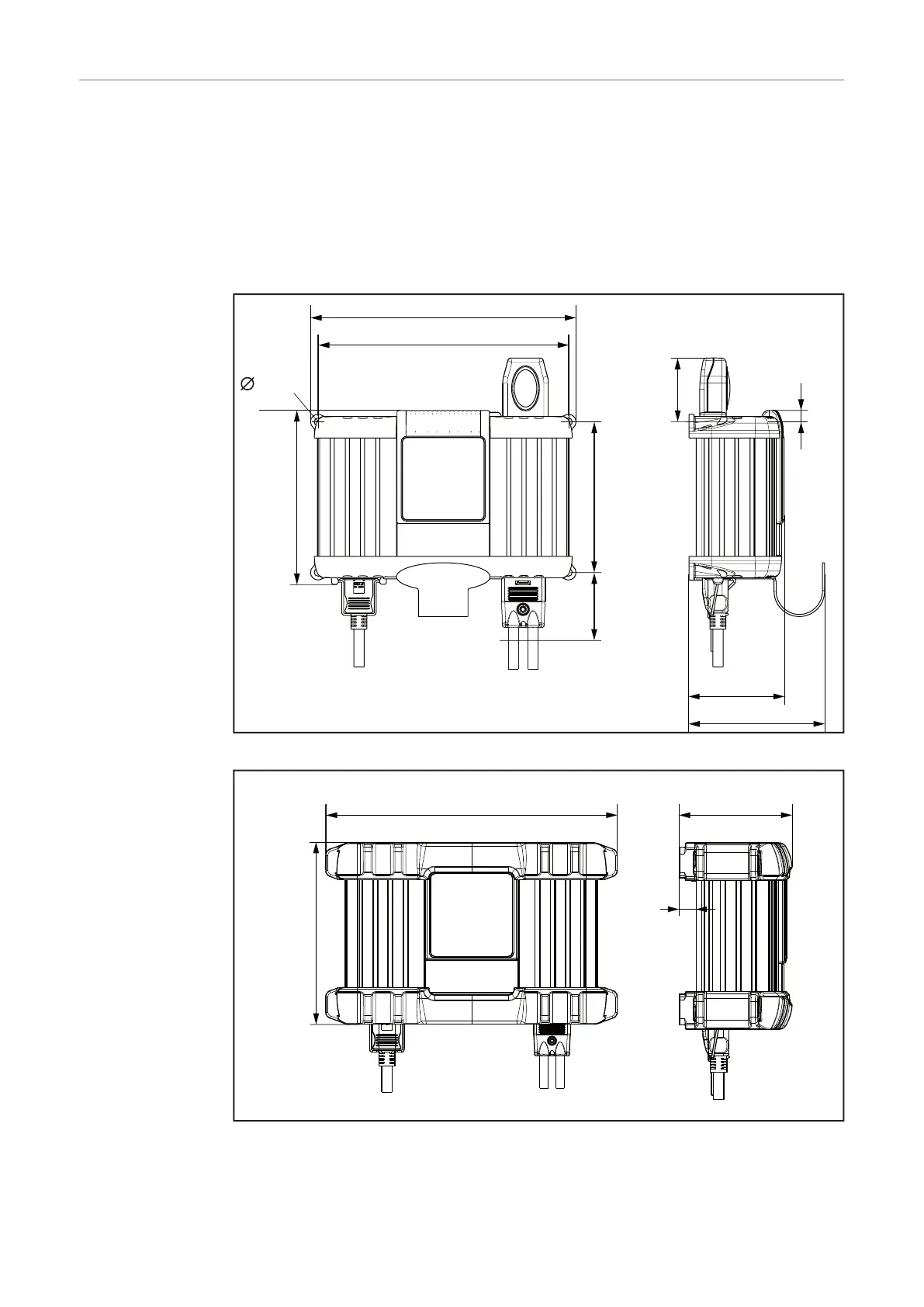
Installation If installing the charger on a firm base, use the drilling template enclosed in the
packaging.
If the charger is installed in a switch cabinet (or a similar sealed area), then
forced-air ventilation must be provided to ensure adequate heat dissipation.
There must be a clearance of 10 cm (3.94 in.) all around the charger.
The space requirement measurements in mm (inches) illustrated below are given
to ensure that there is easy access to the plug connections:
247 (9.72)
88 (3.46)
126 (4.97)
140 (5.51)
60 +20*
(2.36 + .79*)
70 + 20*
(2.76 + .79)
11 + 5*
(.43 + .2*)
162 (6.38)
233 (9.17)
6,5 (.26)
*Space for installation/removal
100 (3.94)
15,5 (.61)
168
(6.61)
270 (10.63)
Space requirements with edge protector
19