35
EN-US
CAUTION!
Danger due to overloading on the inverter.
This may result in damage to the inverter.
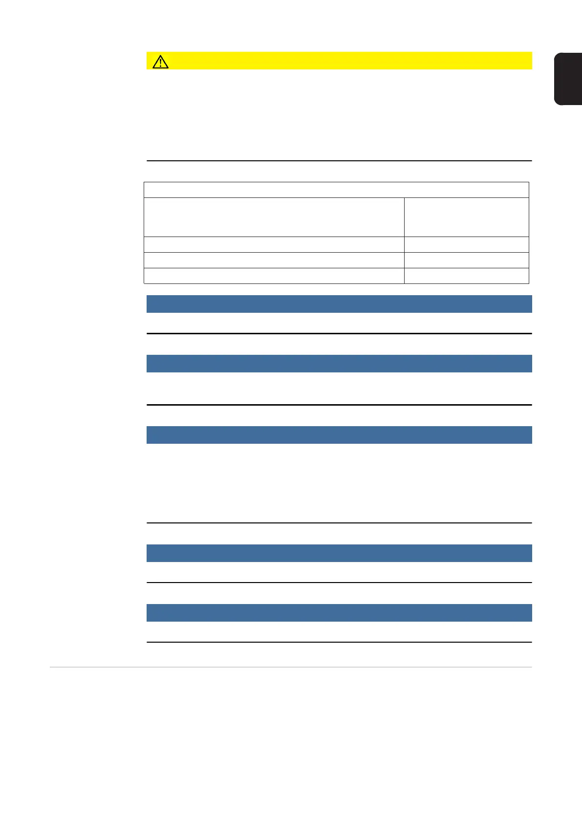
► Observe the maximum current carrying capacity of the various power categories (see
Table A).
► Only connect a maximum of 33 A to each DC terminal.
► Connect the DC+ and DC- cables to the correct DC+ and DC- terminals on the inverter.
► Observe the maximum DC input voltage.
NOTE!
Solar modules exposed to light supply current to the inverter.
NOTE!
When using the cable inlets at the back, take care to seal them according to protec-
tion class NEMA4X before operating outdoors.
NOTE!
When connecting aluminum cables:
► follow all national and international guidelines regarding the connection of aluminum
cables
► follow the instructions of the cable manufacturer
► perform an annual check to ensure that the cables are firmly attached according to the
proper torque
NOTE!
When connecting DC cables, ensure the polarity is correct.
NOTE!
Form a min. 4 in. (100 mm) cable loop with all cables.
String Fuses Only applies to device type Fronius Symo 15.0-3 208 and device types Fronius Symo
15.0-3 480 / 20.0-3 480 / 22.7-3 480 / 24.0-3 480 with the "Ecofuse" option:
The use of string fuses in the Fronius Symo provides additional fuse protection for solar
modules.
The maximum short circuit current I
SC
, the maximum module backfeed current I
R
and the
specification of the maximum string fuse value in the module data sheet of the respective
Table A
Power category Maximum current carrying
capacity
MPP1 / MPP2
10.0-3 208–240/12.0-3 208–240/10.0-3 480/12.5-3 480 25 A / 16.5 A
15.0-3 208 50 A
15.0-3 480/17.5-3 480/20.0-3 480/22.7-3 480/24.0-3 480 33 A / 25 A

 Loading...


