44
7
IMPORTANT! If data communication cables are wired into the inverter, observe the follow-
ing points:
- Provide separate conduits for data communication cables
- Lay data communication cables in the supplied conduit
- Knock out the appropriate opening
- Cleanly deburr the knocked-out opening
- Clip the inverter onto the mounting bracket
- Guide the data communication cables through the cable glands from behind
- When pivoting the inverter, ensure that the cables are not trapped, kinked, or dam-
aged in any other way. Do not loop the data communication cables.
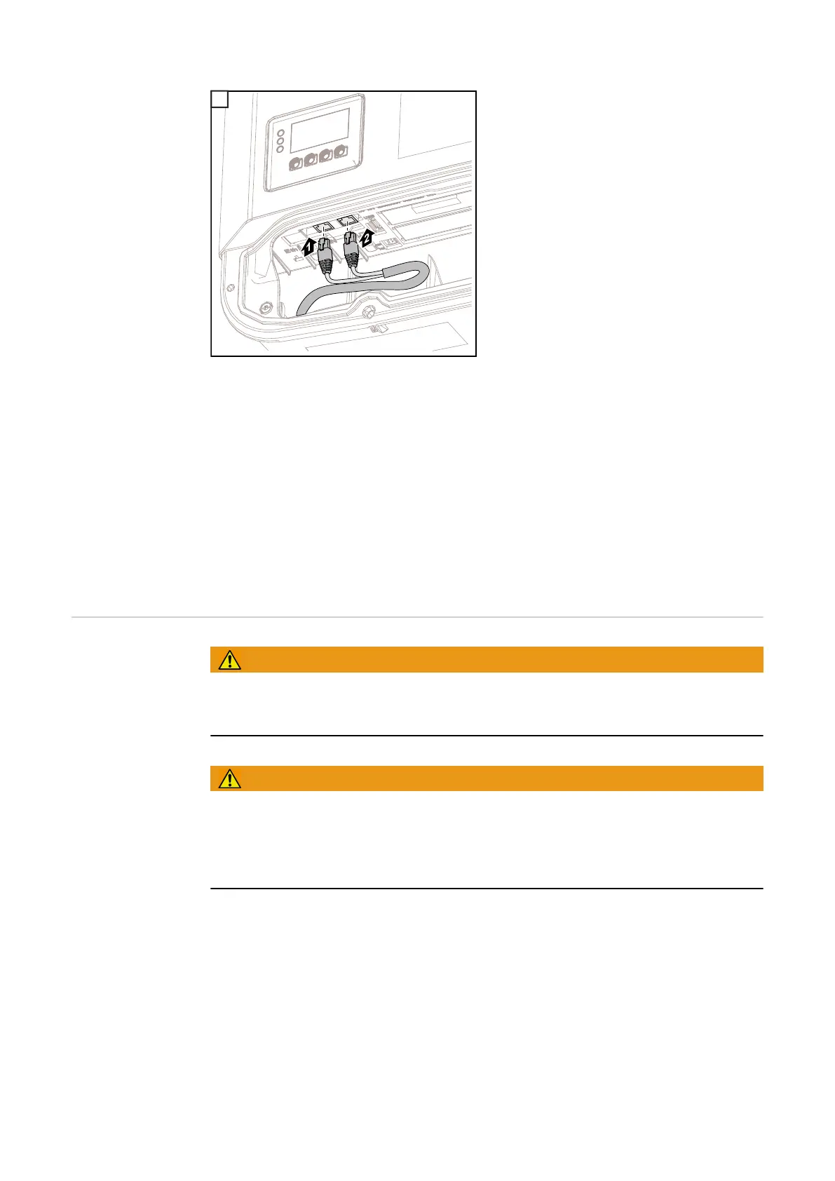
- Lay the data communication cables in the data communication area of the inverter and
connect to the Solar.Net “IN” and “OUT” connections.
Plug the termination plugs into the remaining Solar.Net connections.
Installing Data-
manager in the In-
verter
WARNING!
Danger of residual voltage from capacitors.
An electric shock can be fatal.
► Wait until the capacitors have discharged. Discharge takes 5 minutes.
WARNING!
An inadequate ground conductor connection can cause serious injury and damage
to property.
► The housing screws provide an adequate ground conductor connection for grounding
the housing and should not be replaced under any circumstances by other screws that
do not provide a reliable ground conductor connection.
IMPORTANT! Follow general ESD guidelines when handling option cards.
IMPORTANT! Only one Fronius Datamanager in master mode is permitted per Fronius
Solar.Net Ring. Switch other Fronius Datamanagers to slave mode or remove them.
Unused option card slots can be closed by replacing the cover (item number
42,0405,2094), or an inverter without Fronius Datamanager (light version) can be used.
IMPORTANT! Only knock out one opening for the PC board when installing a data man-
ager in the inverter.
7

 Loading...


