61
EN-US
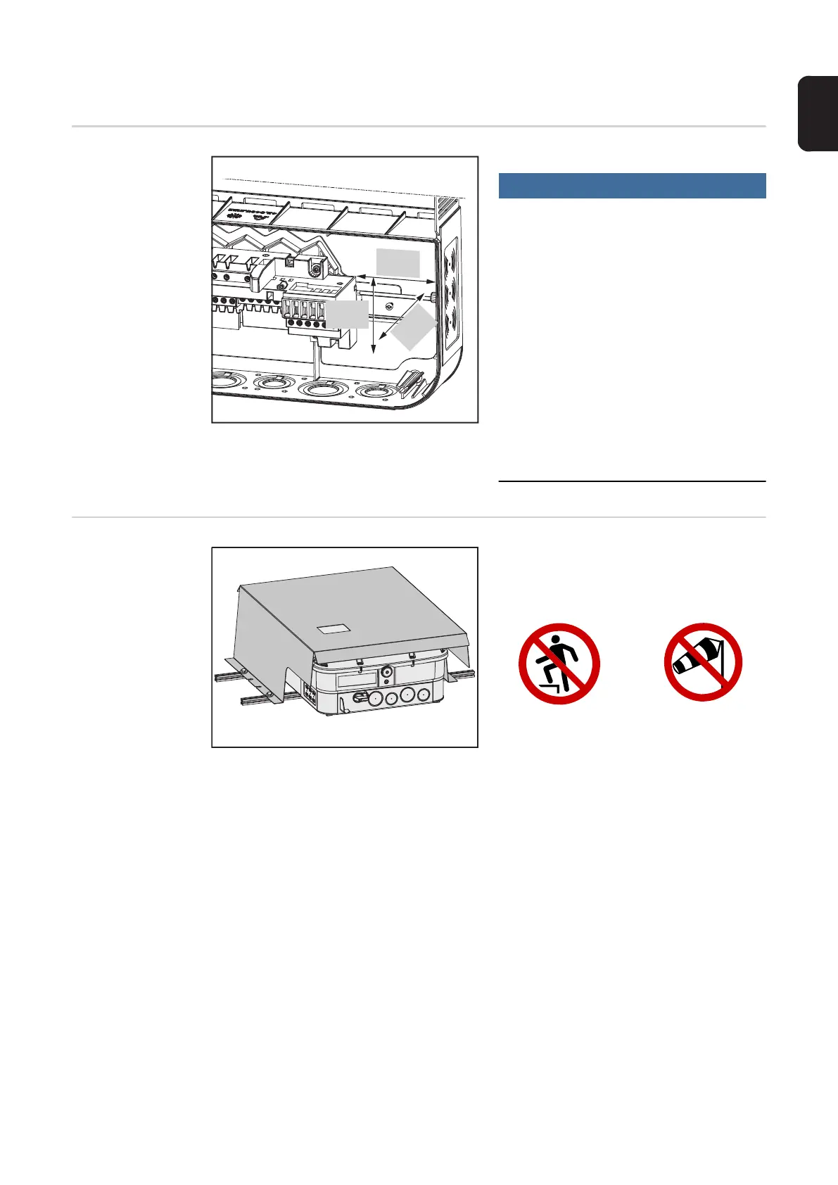
Options
Options
NOTE!
A DIN rail is provided in order to mount
accessory electrical devices including,
but not limited to, overcurrent protecti-
on, metering, radio or cellular modem.
Maximum size for mounting of all devices is
4 w x 4.75 l x 2.75 inches. The installer ta-
kes responsibility for any undesired effect
on the inverter by installing an electrical de-
vice in this area. Caution should be taken
when installing a device that may output si-
gnificant amounts of heat or radio interfe-
rence. Always ensure that the device does
not inhibit the inverter from closing and se-
aling properly. Any questions about device
eligibility should be directed toward techni-
cal support.
OPTION
'ShadeCover'
- Use the ShadeCover when the inverter
is exposed to direct sunlight
- Use 4 screws for proper mounting
4.75 in.
120 mm
4 in.
100 mm
2.75 in.
70 mm
NO MOUNTING

 Loading...


