Introduction and Setup 13
1.5.2 Rear Panel Layout
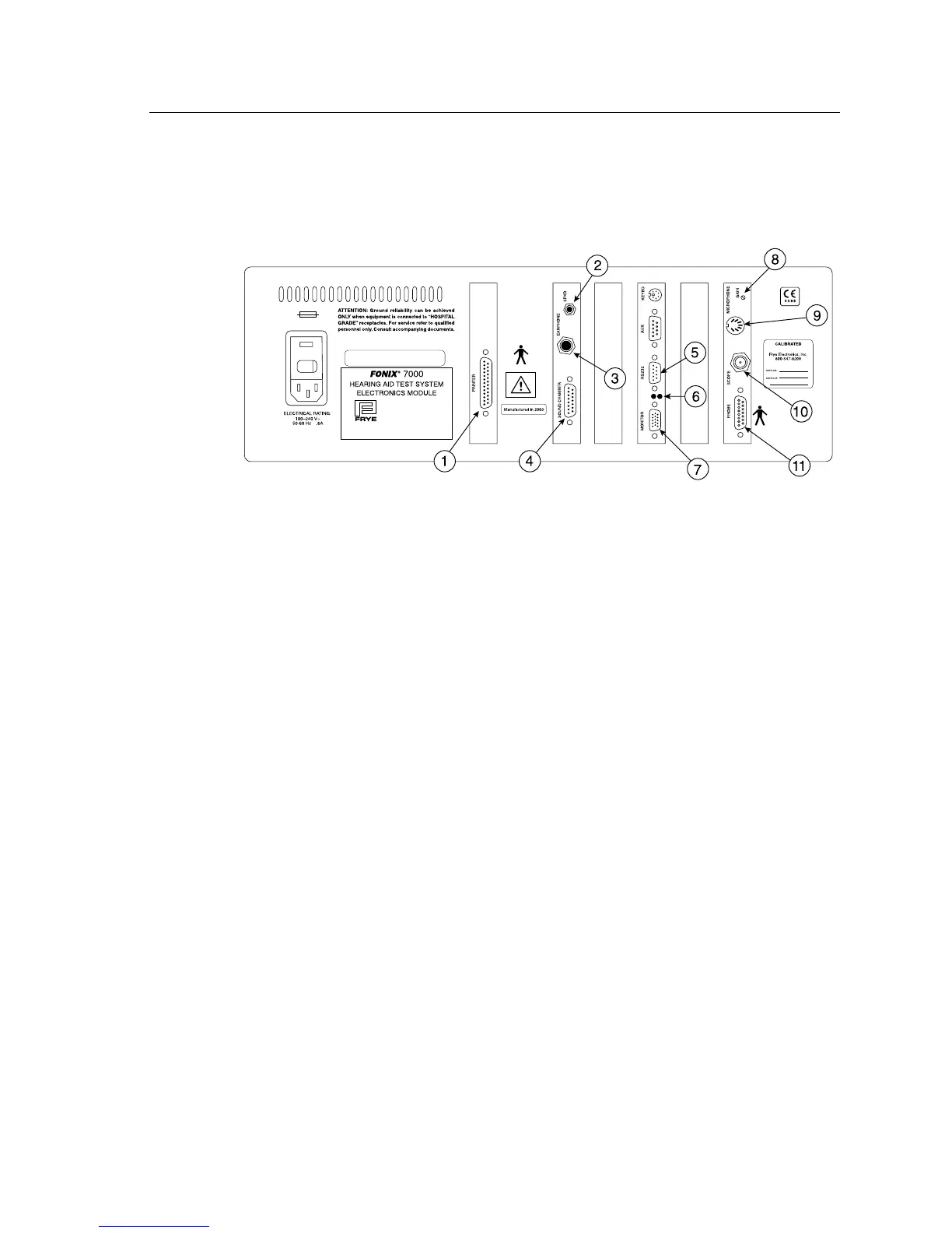
The rear panel of the 7000 test system contains most of the external connec-
tions for the analyzer. See Figure 1.5.2 for a diagram of the back panel.
FONIX 7000 Serial No. 1234
Made in Tigard, Oregon, USA
by
Frye Electronics, Inc.
Frye Electronics products are protected by
U.S.
and/or foreign patents and/or patents pending
T630 mAL
Figure 1.5.2—Back panel
1. PRINTER: Connects an external printer to the 7000 test system.
2. SPKR: Connects the sound field speaker for real-ear measure-
ments.
3. EARPHONE: Connect a insert earphone to the analyzer for RECD mea-
surements. A 50 ohm earphone should always be used, to
avoid harm to the earphone.
4. SOUND
CHAMBER: Connects the main module to the sound chamber.
5. RS232: Connects the 7000 test system to a personal computer.
6. RS232 LEDs: The red LED indicates the analyzer is sending a poll. This
will flash whether or not a computer is connected. The
green LED indicates the analyzer is receiving a command
from a connected computer.
7. MONITOR: Connects the main module to a video monitor.
8. GAIN: Adjusts the calibration of the M1950E microphone.
9. MICROPHONE: Connects the M1950E microphone.
10. SCOPE: Connects to an external scope for external measuring pur-
poses.