10
Before mounting the option, perform the wiring for the main circuit terminals and control circuit
terminals.
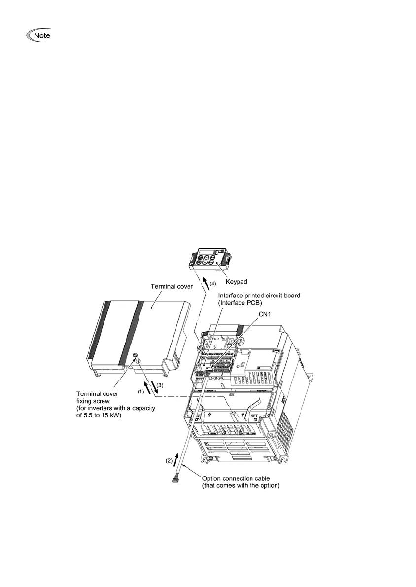
(1) Remove the terminal cover from the inverter.
Note: For inverters with a capacity of 5.5 to 15 kW, you need to remove the terminal cover fixing screw to remove
the terminal cover.
For details on how to remove the terminal cover, refer to the FRENIC-Multi Instruction Manual
(INR-SI47-1094-E), Chapter 2, Section 2.3 "Wiring."
(2) Connect the option connection cable to the CN1 connector on the interface printed circuit board (interface
PCB) on the inverter.
Use the short cable for inverters with a capacity of 3.7 kW or below, and the long cable for the ones with a
capacity of 5.5 kW or above.
(3) Mount the terminal cover.
For details on how to mount the terminal cover, refer to the FRENIC-Multi Instruction Manual
(INR-SI47-1094-E), Chapter 2, Section 2.3 "Wiring."
(4) Push the hooks provided on both sides of the keypad and pull the keypad up and out of the inverter.
For details on how to remove the keypad, refer to the FRENIC-Multi Instruction Manual
(INR-SI47-1094-E), Chapter 2, Section 2.4 "Mounting and Connecting a Keypad."
Figure 3.1 Connecting the Option Connection Cable to the Interface PCB and Removing the Keypad
(For inverters with a capacity of 11 and 15 kW)