EasyManuals Logo

Fuji Electric FRENIC-Multi OPC-E1-DEV User Manual

Fuji Electric FRENIC-Multi OPC-E1-DEV
42 pages
To Next Page IconTo Next Page
To Previous Page IconTo Previous Page
Page #14 background imageLoading...
Page #14 background image
12
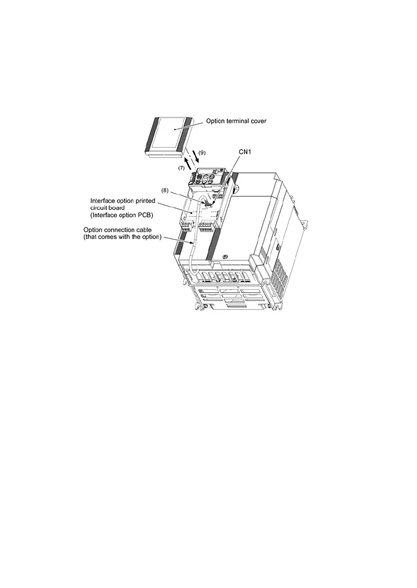
(7) Slightly pull the bottom of the option terminal cover towards you and remove it downward.
(8) Connect the other end of the option connection cable (whose end has been connected to the interface PCB
on the inverter in step (2) above) to the CN1 connector on the interface option printed circuit board
(interface option PCB).
(9) Mount the option terminal cover.
First fit the bosses on the top of the cover into the square holes provided in the option, and then push the
bottom of the cover until it snaps into place.
Figure 3.3 Connecting the Option Connection Cable to the Interface Option PCB

Questions and Answers:

Question and Answer IconNeed help?

Do you have a question about the Fuji Electric FRENIC-Multi OPC-E1-DEV and is the answer not in the manual?

Fuji Electric FRENIC-Multi OPC-E1-DEV Specifications

General IconGeneral
BrandFuji Electric
ModelFRENIC-Multi OPC-E1-DEV
CategoryControl Unit
LanguageEnglish

Related product manuals