22
(3) Fuji Drive Assembly Instance
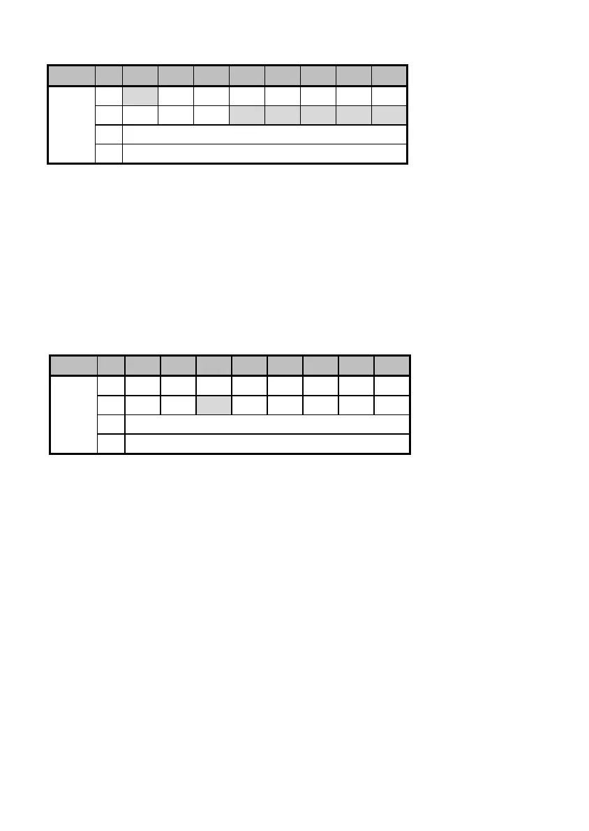
Output (from master to this option): o31=100
Instance byte bit 7 bit 6 bit 5 bit 4 bit 3 bit 2 bit 1 bit 0
0 - X5 X4 X3 X2 X1 REV FWD
1 RST XR XF - - - - -
2 Frequency command p.u. (lower byte)
100
3 Frequency command p.u. (upper byte)
FWD: 1 = Run forward command
REV: 1 = Run reverse command
X1 to X5: Communication terminal block command
(The function to be performed is specified by E01 to E05).
XF, XR: Communication terminal block command
(The function to be performed is specified by E98 and E99).
RST: 1 = Reset the alarm (fault) condition.
Frequency command p.u.: Specifies the ratio of the frequency relative to the maximum frequency
(defined by F03 in Hz) being assumed as 20000.
Frequency command p.u. = Frequency command (Hz)/F03 (Hz) × 20000.
Input (from this option to master): o32=101
Instance byte bit 7 bit 6 bit 5 bit 4 bit 3 bit 2 bit 1 bit 0
0 VL TL NUV BRK INT EXT REV FWD
1 BUSY ERR - RL ALM DEC ACC IL
2 Frequency output p.u. (lower byte)
101
3 Frequency output p.u. (upper byte)
FWD: During forward rotation
REV: During reverse rotation
EXT: During DC braking (or during pre-exciting)
INT: Inverter shut down
BRK: During braking
NUV: DC link bus voltage established (0 = undervoltage)
TL: During torque limiting
VL: During voltage limiting
IL: During current limiting
ACC: During acceleration
DEC: During deceleration
ALM: Alarm relay (for any fault)
RL: Run or speed command from communication enabled
ERR: Function code access error
BUSY: During function code data writing
Frequency output p.u.: Specifies the ratio of the frequency relative to the maximum frequency (defined by
F03 in Hz) being assumed as 20000.