EasyManua.ls Logo

Fuji Electric FRENIC-Multi OPC-E1-DEV User Manual

Fuji Electric FRENIC-Multi OPC-E1-DEV
42 pages
To Next Page IconTo Next Page
To Previous Page IconTo Previous Page
Page #32 background imageLoading...
Page #32 background image
30
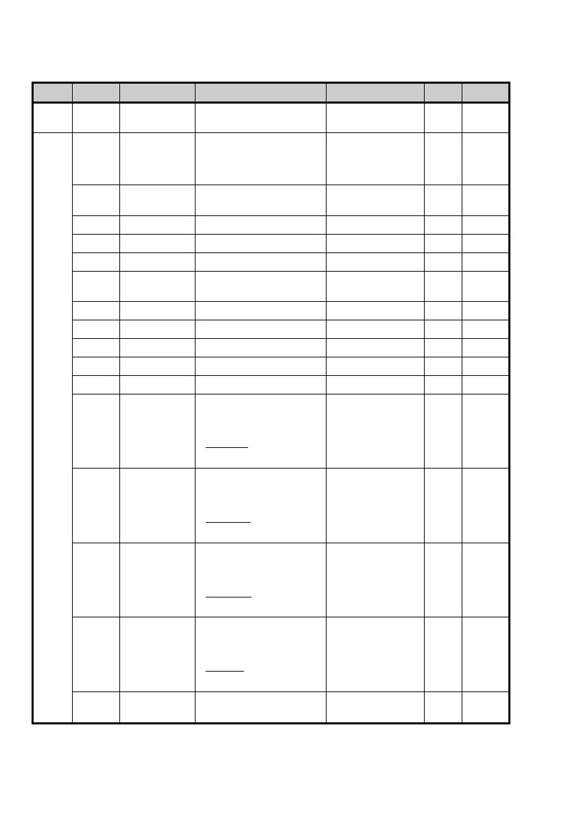
(4) AC/DC Drive object (Class 2A hex.)
This object monitors the current speed command settings and the current speed of the inverter, and configures
their related settings. It also monitors the output data issued from the inverter.
Instance Attribute Name Description Value (hex.) R/W Data size
0 01 hex Revision Revision number of AC/DC
Drive object
0001 R Word
1 03 hex AtReference Speed arrival 00: Stopped/
Accelerating or
decelerating
01: Speed arrival
R Byte
04 hex NetRef Switching speed command
source
00: Inverter
01: DeviceNet
R/W Byte
06 hex DriveMode Run mode. Fixed at 0. 00: Unique to vendor R Byte
07 hex SpeedActual Speed monitor (r/min) Actual speed R Word
08 hex SpeedRef Speed command (r/min) -32768 to 32767 r/min R/W Word
09 hex CurrentActual Output current
(in units of 0.1 A)
Output current R Word
11 hex OutputVoltage Output voltage (V) Output voltage R Word
12 hex AccelTime Acceleration time (ms) 0 to 65535 ms R/W Word
13 hex DeccelTime Deceleration time (ms) 0 to 65535 ms R/W Word
14 hex LowSpdLimit Lower limit speed (r/min) 0 to 32767 r/min R/W Word
15 hex HighSpdLimit Maximum speed (r/min) 0 to 32767 r/min R/W*
1
Word
16 hex SpeedScale Change the speed scale
(r/min) all at once, as
calculated below.
SpeedScale
2
r/min
-15 to 15
(Factory default: 0)
R/W Byte
17 hex CurrentScale Change the current scale
(0.1 A) all at once, as
calculated below.
leCurrentSca
2
A0.1
-15 to 15
(Factory default: 0)
R/W Byte
1B hex VoltageScale Change the voltage scale (V)
all at once, as calculated
below.
leVoltageSca
2
V
-15 to 15
(Factory default: 0)
R/W Byte
1C hex TimeScale Change the time scale (ms)
all at once, as calculated
below.
TimeScale
2
ms
-15 to 15
(Factory default: 0)
R/W Byte
1D hex RefFromNet Current speed command
source
00: Inverter
01: DeviceNet
R Byte
*
1
"Read-only" while the inverter is running.

Questions and Answers:

Fuji Electric FRENIC-Multi OPC-E1-DEV Specifications

General IconGeneral
BrandFuji Electric
ModelFRENIC-Multi OPC-E1-DEV
CategoryControl Unit
LanguageEnglish

Summary

Preface

How this manual is organized

Overview of the manual's chapter structure and content.

Related Publications

Lists other manuals relevant to the DeviceNet interface option.

Safety precautions

Details important safety information and warnings for using the product.

Operational Procedures

Installation and Wiring

Instructions for installing and wiring the DeviceNet interface option.

Operation

Guidance on operating the inverter with the DeviceNet interface option.

Maintenance and Inspection

Procedures for maintaining and inspecting the DeviceNet option.

Disposal

Others

Chapter 1: Before Using This Option

1.1 Acceptance Inspection

Checks to be performed upon delivery of the DeviceNet interface option and accessories.

1.2 Applicable Inverters

Lists the FRENIC-Multi inverters and ROM versions compatible with the option.

Chapter 2: Basic Functions and Settings

2.1 DeviceNet Interface Option Inside View

Illustrates the internal components of the DeviceNet interface option.

2.2 DIP Switch

Configures communication data rate and node address using the DIP switch.

2.3 LED Status Indicators

Details the meaning of the MS and NS LEDs indicating hardware and network status.

2.4 RJ-45 Connector and Terminal Blocks

Covers RJ-45 connector and terminal blocks for power and DeviceNet connections.

Chapter 3: Installation of This Option

Chapter 4: Wiring and Cabling

4.1 Basic Connection Diagram

Illustrates the fundamental wiring connections for the FRENIC-Multi and DeviceNet option.

4.2 Wiring for Power Supply Terminal Block

Details the wiring procedures for the 24V power supply terminal block.

4.3 Wiring for DeviceNet Terminal Block

Explains the wiring connections for the DeviceNet communication cable.

4.4 Turning ON the Optional 24 V Power Supply

Provides instructions on the correct ON/OFF timing for the option and inverter.

Chapter 5: Configuring Inverter's Function Codes for DeviceNet Communication

Chapter 6: Establishing a DeviceNet Communications Link

Chapter 7: I/O Message

7.1 Overview

Explains I/O Message as a cyclic communication process between master and slave.

7.2 I/O Assembly Instances: Selection and Setup

Details the selection and setup of I/O assembly instances for various control modes.

7.3 An Example of Actual I/O Communication Data

Provides a practical example of I/O data in Extended Speed Control Instance.

Chapter 8: Explicit Message

8.1 Overview

Explains Explicit Message for arbitrary access to DeviceNet variables and function codes.

8.2 Objects to be Used in Explicit Message

Describes objects related to the option and inverter for explicit message communication.

8.3 Error Code List for Explicit Message Errors

Lists explicit message errors, their codes, descriptions, and recovery methods.

Chapter 9: Inverter Reaction to DeviceNet Communications Errors

Chapter 10: Alarm Code List

Chapter 11: Troubleshooting

Chapter 12: Specifications

12.1 General Specifications

Lists general specifications of the DeviceNet interface option and applicable inverter.

12.2 DeviceNet Specifications

Details the specifications related to DeviceNet communication protocols and capabilities.

Related product manuals