1-4
You can monitor the digital input status of the PG interface card with the inverter keypad. For
details, refer to the FRENIC-Multi Instruction Manual (INR-SI47-1094-E), Chapter 3, Section 3.4.5
"Checking I/O signal status."
1.3.3 Wiring between the PG interface card and PG
• Turn the inverter's power OFF and wait for at least five minutes before starting
connection.
• Qualified electricians should carry out wiring.
Otherwise, electric shock could occur.
• Noise may be emitted from the inverter, motor and wires. Implement appropriate
measure to prevent the nearby sensors and devices from malfunctioning due to such
noise.
Otherwise, an accident could occur.
Wire the PG to the PG interface card, observing the following precautions and referring to the
connection diagrams given in Figures 2.1 to 2.3.
(1) Turn the inverter's power OFF.
(2) Use a shielded wire for wiring between the PG and the PG interface card.
(3) To prevent malfunction due to noise, keep the wiring away from the main circuit wiring of the
inverter and the power wiring of other devices as far as possible (at least 10 cm). Do not route
them in the same duct.
(4) Complete the wiring for the PG before turning the inverter's power ON.
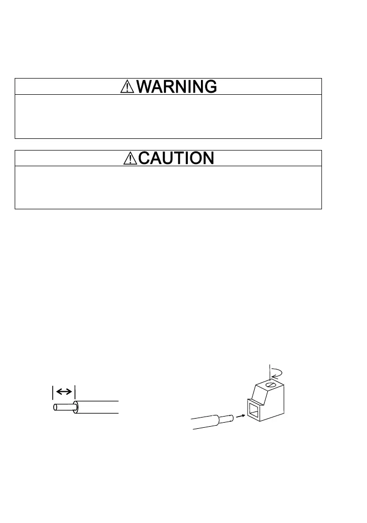
(5) The wire size applicable to the option connection terminal on the inverter is AWG 18-24.
When using a wire with its end being stripped, strip its end by 5 to 7 mm. When using a ferrule,
use a vinyl-insulated ferrule.
Loosen the fixing screw, insert the wire end into the opening of the terminal block, and tighten
the screw.
Figure 1.6 Stripping the Wire End Before Connection to Terminal Board
Recommended wire: AWG 18-24 for rated temperature 105°C (UL)
5 to 7 mm

 Loading...


