7-9
7.8 Assignment of PG Terminals When Shared
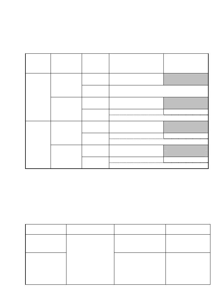
Table 7.12 lists input assignments for terminals [XA], [XB], [XZ], [YA], [YB] and [YZ] when the
positioning control, speed control with PG and speed control with pulse rate input share the PG
terminals
The specifications of those terminals when shared differ from the ones when not shared.
Table 7.12 Function Assignments of PG Terminals
Pulse train
input,
F01/C30
data is 12.
Speed control
with PG,
F42/A14 data
is 3 or 4.
Positioning
control,
S/R is
assigned.
Normal mode
(Except the right column
mode)
Serial pulse receiving
mode,
SPRM is ON
X: Pulse monitor (o01)
No
Y: Pulse monitor (o01)
X: Serial pulse (J86)
No
Yes
Y: Positioning control (o01)
X: Pulse monitor (o01)
No
Y: Speed control (o01)
X: Positioning control (o01) X: Serial pulse (J86)
No
Yes
Yes
Y: Speed control (o01)
X: Pulse train input (o01)
No
Y: Pulse monitor (o01)
X: Pulse train input (o01) X: Serial pulse (J86)
No
Yes
Y: Positioning control (o01)
X: Pulse train input (o01)
No
Y: Speed control (o01)
X: Pulse train input (o01) X: Serial pulse (J86)
Yes
Yes
Yes
Y: Speed control / Positioning control (o01)
Symbol "X" in the above table stands for PG terminals [XA], [XB] and [XZ]. Specify their input modes
with the data in the ones place of function code o01.
Symbol "Y" stands for PG terminals [YA], [YB] and [YZ]. Specify their input modes with the data in the
tens place of function code o01.
Switching to the serial pulse receiving mode with SPRM involves switching of the input mode, so the
idle time insertion is required for a stable switching as listed below.
Table 7.13 Idle Time Required for Stable Mode Switching by SPRM
Function switching
When SPRM is turned
from OFF to ON:
When SPRM is turned
from ON to OFF:
Remarks
Positioning control
to/from serial pulse
receiving
Do not input the serial
pulse within 100 ms
before or after SPRM is
turned OFF.
--
Pulse train input
to/from serial pulse
receiving
Insert a minimum of 100
ms idle time before the
start of the serial pulse
receiving input after
SPRM is turned ON.
Stop the serial pulse
receiving input before a
minimum of 100 ms before
SPRM is turned OFF.
Start the pulse train input
within 100 ms after SPRM
is turned OFF.
During the "serial pulse
receiving mode (SPRM
being ON) + 100 ms,"
the inverter holds the
pulse train input count
applied when SPRM is
turned ON.

 Loading...


