6-2
6.3 Function Code List
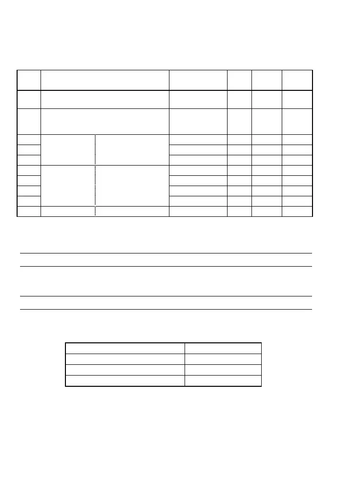
Table 6.4 lists function codes to be used for speed control with PG.
Mounting the PG interface card can display o codes.
Table 6.4 Related Function Codes
Code Name Data setting range Unit
Default
setting
Change
when
running
F42
(A14)
Control Mode Selection 1
(Control Mode Selection 2)
0 to 4 - 0 N
o01
Command/
Feedback Input
(Input mode)
0, 1, 2,
10,11,12,
20,21,22
- 0 N
o02 Speed Control (P Gain) 0.01 to 200.00 Times 10.00 Y
o03 (Integral time) 0.000 to 5.000 s 0.100 Y
o04 (Filter time constant) 0.000 to 5.000 s 0.020 Y
o09 (Encoder pulse resolution) 20 to 3600 P/R 1024 N
o10 (Filter time constant) 0.000 to 5.000 s 0.005 Y
o11 (Pulse count factor 1) 1 to 9999 - 1 N
o12
Feedback Input
(Pulse count factor 2) 1 to 9999 - 1 N
o13 Speed Control (Output limiter) 0.00 to 100.00 % 100.00 Y
6.4 Function Code Details
F42 Control Mode Selection 1 (A14: Control Mode Selection 2)
To select the V/f control with PG interface or dynamic torque vector control with PG interface,
set the F42 (A14) data to "3" or "4," respectively.
o01 Command/Feedback Input (Input mode)
This function code switches the feedback pulse input mode with the data in the tens place as
listed below.
Table 6.5 Data for o01
Feedback pulse input mode Data for o01
B phase pulse input 0
Forward/reverse pulse input 1
A/B phase pulse input 2

 Loading...


