7-1
Chapter 7 POSITIONING CONTROL
Using PG feedback signals enables positioning control. The inverter internally counts the feedback
pulses and controls the motor so that the control object moves from the previously specified start
point, decelerates and switches to the creep speed operation to arrive at the specified stop position.
The positioning control can be enabled concurrently with the frequency control with pulse rate input
and speed control with PG.
7.1 Specifications
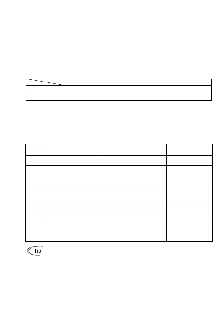
Table 7.1 lists the specifications of positioning control.
Table 7.1 Specifications of Positioning Control
Item Specifications Remarks
Speed control Range 180 to 3600 r/min
Pulse input Maximum pulse rate 30 kp/s Wiring length: Max. 20 m
7.2 Terminal Functions
Table 7.2 lists terminal functions for the positioning control alone (no concurrent use of the speed
control with PG or frequency control with pulse rate input).
Table 7.2 Terminal Functions
(no concurrent use of speed control with PG or frequency control with pulse rate input)
Terminal
symbol
Name Functions Remarks
PI Power input terminal
Receives power for the PG from an
external source.
PO Power output terminal Outputs power to the PG.
CM Common terminal Common terminal for the PG power.
XA
Command input terminal
for A phase pulse train
Receives an A phase command
pulse train.
XB
Command input terminal
for B phase pulse train
Receives a B phase command
pulse train.
XZ -- Reserved.
Specify the input mode
with J86.
YA
Feedback input terminal
for A phase pulse train
Receives an A phase feedback
pulse train.
YB
Feedback input terminal
for B phase pulse train
Receives a B phase feedback pulse
train.
Specify the input mode
with o01.
YZ
Feedback input terminal
for Z phase pulse train
Receives a Z phase feedback pulse
train.
No connection needed if
no preset positions are
specified with J76 and
J77.
• The pulse count of [XA], [XB], [YA], [YB] and [YZ] inputs can be displayed on the
keypad by using Menu #4, "I/O Checking," Check items 4_15, 4_17, and 4_18. Fo
details, refer to the inverter's instruction manual. (See the description of function code
E52.)
• When the positioning control is enabled concurrently with the speed control with PG o
frequency control with pulse rate input, the specifications of terminals [XA], [XB], [XZ],
[YA], [YB], and [YZ] differ from the ones listed above. For details, refer to Section 7.8
"Assignment of PG Terminals When Shared." (Refer to the description of function code
o01.)

 Loading...


