6-4
o11
o12
Feedback Input (Pulse count factor 1)
Feedback Input (Pulse count factor 2)
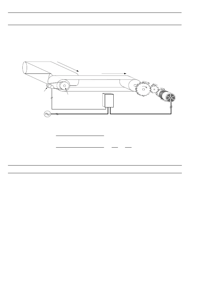
These function codes specify pulse count factors 1 and 2.
Use these function codes when the motor shaft speed differs from the encoder (PG) shaft
speed depending upon a transmission reduction ratio.
Refer to Figure 6.1 and the expressions below for calculation of the count factors.
[YA],[YB]
Conveyer
Motor
Gear train
(Transmission
ratio: a/b)
Power
supply
L1/R, L2/S, L3/T
Pulley
(Transmission
ratio: c/d)
No. of teeth: b
No. of teeth: a
No. of teeth: a
Radius: c
Radius: d
Inverter
FRN-E1S
PG
U, V, W
Figure 6.1 Speed Control Model Using a PG
Pulse count factor 2 (o12)
Motor shaft speed =
Pulse count factor 1 (o11)
× Encoder shaft speed
Pulse count factor 2 (o12) b d
Pulse count factor 1 (o11)
=
a
×
c
o13 Speed Control (Output limiter)
This function code specifies the output limit percentage for the speed controller (PI controller).
Specification of 100.00% is equivalent to the maximum speed (maximum frequency).
To suppress the frequency control amount (PI controller output) to the extent of the motor's
slip frequency in the speed control mode, use this function.

 Loading...


