2-1
Chapter 2 CONNECTION DIAGRAMS
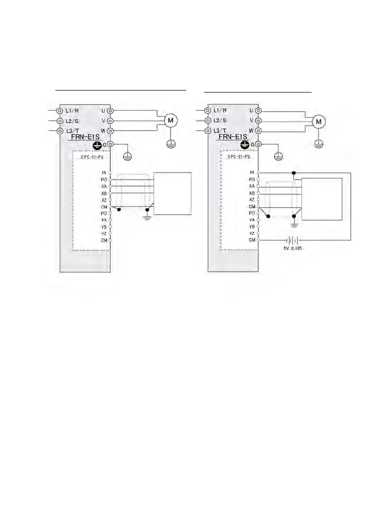
2.1 For Frequency Control with Pulse Rate Input
Figure 2.1 shows connection diagram examples for frequency control with pulse rate input.
Figure 2.1 Connection Diagrams for Frequency Control with Pulse Rate Input
(Note 1) For details about applicable PG specifications, refer to Table 1.2 in Chapter 1,
Section 1.3.1 "PG specifications."
Pulse train
generator
or
PG (Note 1)
Pulse train
generator
or
PG (Note 1)
When using inverter internal power suppl
When using external power suppl

 Loading...


