1-3
1.3 PG Specifications and PG Mounting Instructions
• Using the PG whose specifications are not satisfied may cause the inverter and
equipment to malfunction.
Doing so could cause failure or injuries.
1.3.1 PG specifications
Table 1.2 lists the applicable PG specifications.
Table 1.2 Specifications of Applicable PG and PG Interface Card
Item Specifications
Encoder system Incremental system
Pulse resolution 20 to 3000 P/R
Applicable PG
Input power requirements
5 VDC ±10% / 100 mA
(200 mA, when a single PG is mounted.)
Internal power supply +5 VDC ±10% / 200 mA
PG power supply
External power supply +5 VDC ±10%, 200 mA or more
Output signal
Open collector (pull-up resistor: 620Ω)
Complementary (totem-pole push-pull) voltage output
Note 1: The wiring length between the PG and inverter should not exceed 20 m.
Note 2: When the PG power is 200 mA or more, use an external power supply.
Note 3: The external power supply should satisfy the voltage specifications of the PG.
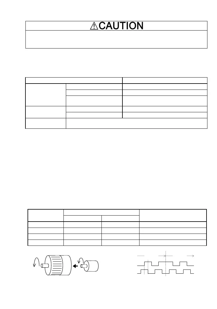
1.3.2 Mounting the PG to the motor
The counterclockwise rotation when viewed from the motor output shaft is regarded as "forward
rotation" (see Figure 1.4). During rotation in the forward direction, the PG output pulse forms the
forward signal as shown in Figure 1.5 (B phase advances 90 degrees from A phase). During
rotation in the reverse direction, the PG output pulse forms reverse signal (A phase advances 90
degrees from B phase).
Mount the PG to the motor with a coupling, etc.
Table 1.3 lists the correct configurations of commands, rotational directions, and motor wiring. Any
other configuration fails to perform speed control normally.
Table 1.3 Rotational Direction of Encoder and Motor Shafts
Rotational direction
Run command
Encoder shaft Motor shaft
Motor wiring
FWD Forward Forward U V W phases in order
REV Reverse Reverse U V W phases in order
FWD Forward Reverse U V W phases in reverse order
REV Reverse Forward U V W phases in reverse order
Motor
PG
Forward direction
Figure 1.4 Forward Direction of Motor and PG
Forward
signal
Reverse
signal
A phase
B phase
90°
Figure 1.5 Rotational Direction and Output Signal
of PG

 Loading...


