5-60
H04, H05 Auto-reset (Times and Reset interval)
H04 and H05 specify the auto-reset function that makes the inverter automatically attempt to
reset the tripped state and restart without issuing an alarm (for any faults) even if any
protective function subject to reset is activated and the inverter enters the forced-to-stop state
(tripped state). If the protective function works in excess of the times specified by H04, the
inverter will issue an alarm (for any faults) and not attempt to auto-reset the tripped state.
Listed below are the recoverable alarm statuses to be retried.
Alarm status LED monitor displays: Alarm status LED monitor displays:
Overcurrent protection
E
,
E
or
E
Motor overheated
J
Overvoltage protection
W
,
W
or
W
Motor overloaded
N
or
N
Heat sink overheated
J
Inverter overloaded
NW
Braking resistor
overheated
FDJ
Number of reset times (H04)
H04 specifies the number of reset times for automatically escaping the tripped state. When
H04 = 0, the auto-reset function will not be activated.
If the "auto-reset" function has been specified, the inverter may automatically restart and run the
motor stopped due to a trip fault, depending on the cause of the tripping.
Design the machinery so that human body and peripheral equipment safety is ensured even
when the auto-resetting succeeds.
Otherwise an accident could occur.
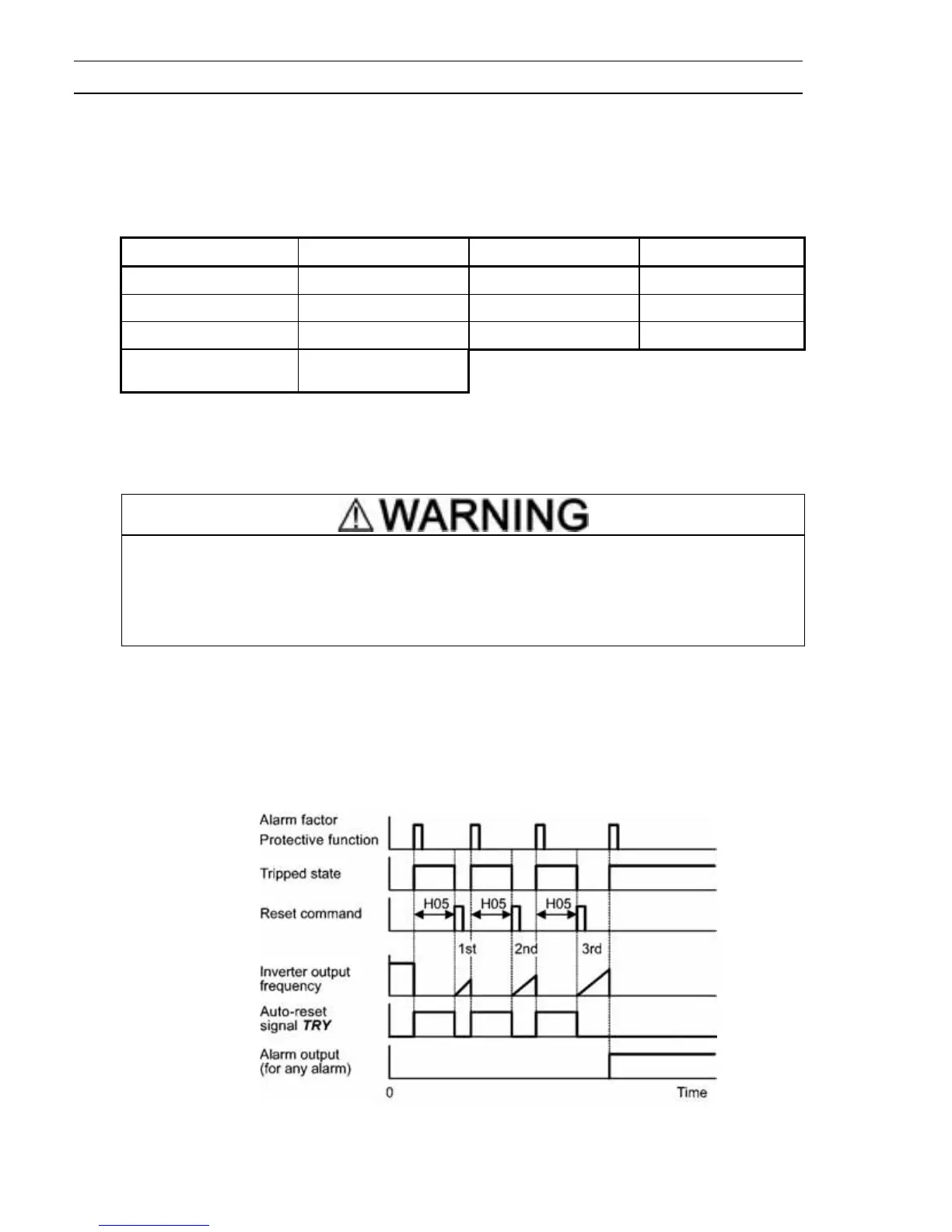
Reset interval (H05)
After the reset interval specified by H05 from when the inverter enters the tripped state, it
issues a reset command to auto-reset the tripped state. Refer to the timing scheme diagrams
below.
<Timing scheme for failed retry (No. of reset times: 3)>
- The reset operation state can be monitored by external equipment via the inverter’s digital
output terminal [Y1], [Y2], or [30A/B/C] to which the TRY is assigned by setting "26" with
function code E20, E21, or E27.