– 8 –
1 Installation/mounting
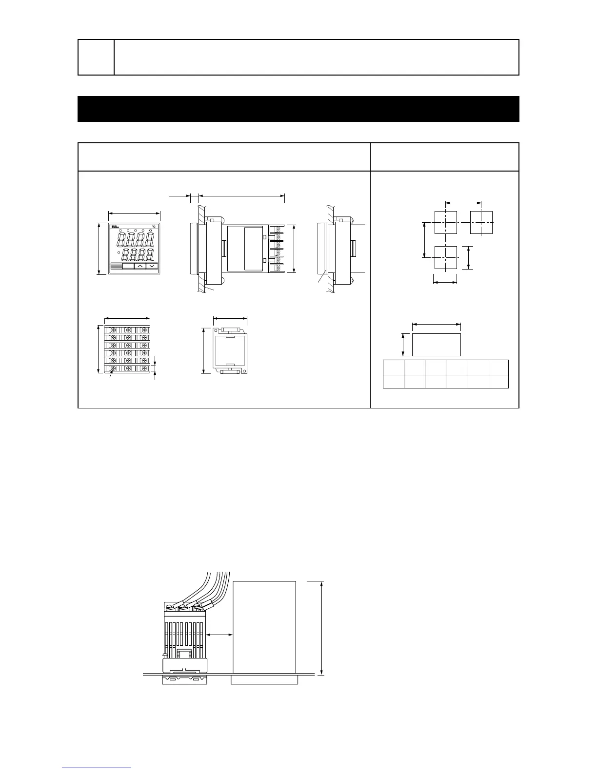
Outline and Panel Cutout Dimensions (Standard type/ Waterproof type)
Note 1
Caution on side by side installation
• With the power supply of 200 VAC or more, a maximum ambient temperature is 45˚C.
(It is recommended to use a fan for cooling.)
Cautions on wiring
• Wiring should be started from the left side terminal (No. 1 to No. 6).
• Use crimped terminals matched to the screw size. Tightening torque should be 0.8 Nm (Since the
case is made of plastic, do not tighten excessively).
• Do not connect anything to terminals not used.
No. 000001T
PXR4TAA1-1YM00-D
MFD 2000-04
AL2AL1C1 C2 AL3
SEL
PXR-4
SV
PV
48
44.8
44.8
79.88
48
Mounting bracket
Panel
Panel thickness 1 to 8mm
Packing
48
44.8
57
6.2
Terminal screw M3×6
13
16
17
18
14
15
7
8
10
11
12
9
1
2
4
5
6
3
63 or more
73 or more
+0.5
a -0
Number
of units
23456
a 93 141 189 237 285
45
+0.5
0
45
+0.5
0
45
+0.5
0
For side by side installation
Note) See the Note1.
Outline dimensions
Panel cutout dimensions
(Unit : mm)
When there is another instrument (larger than 70mm) or a wall on the right side of this controller, be sure
to install the controller keeping a space of more than 30mm.
30 min.
70 or more

 Loading...


