EasyManuals Logo

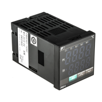
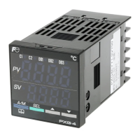
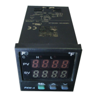
Fuji Electric Model: PXR4 User Manual

Fuji Electric Model: PXR4
32 pages
To Next Page IconTo Next Page
To Previous Page IconTo Previous Page
Page #9 background imageLoading...
Page #9 background image
9
2 Wiring
Terminal Connection Diagram (100 to 240 Vac)
· Common
Relay output
Thermocouple Resistance valve Current/Voltage
Current output
uq!3
iw!4
oe!5
!0r
q
w
e
r
!6
!1t!7
!2y
t
y
!8
· Alarm output1 (AL1)
· Alarm output2 (AL2)
· Heater break
alarm output (AL3)
AC100-240V
Digtal input
CT input
CT input Digtal input
50/60Hz
(+)
(-)
SSR/SSC drive output
Control output1
Alarm output
!3
!4
Note1 : Check the power supply voltage before installation.
Note2 : Connect the I/V unit (250 resistor) (accesory) between the terminal !7 and !8 in case of
currert input.
u
i
u
i
o
!0
o
!0
!1
!2
u
i
u
i
o
!0
o
!0
o
!0
!1
!2
!1
!2
Communicaton (RS485)
Power supply
+
-
!77
!8
Signal input
A
B
B
!6
!77
!8
Control output 2
!3
!4
+
-
Relay output
Control output 2
!1
!2
Relay output
!77
!8
(Note2)
!3
!4
!5
(
Note1
)

Questions and Answers:

Question and Answer IconNeed help?

Do you have a question about the Fuji Electric Model: PXR4 and is the answer not in the manual?

Fuji Electric Model: PXR4 Specifications

Power IconPower
power voltage100 (- 15%) to 240V AC (+10%)
power consumption15V AC or less/240V AC
maximum current20mA or less
Outputs IconOutputs
relay contact output 1SPDT contact, 220VAC / 30VDC 3A
relay contact output 2SPST contact, 220VAC / 30VDC 3A
alarm outputRelay contact (SPST contact) 220V AC / 30V DC 1A
Operating Environment IconOperating Environment
ambient temperature-10 to 50°C
operating ambient humidity90%RH or less
preservation temperature-20 to 60°C

Related product manuals