13
INZ-TN2ZRE-E
Output signal : 4 to 20 mA DC or 0 to 1 V DC (selected when ordering)
Minus lines for the insulation and signal are common from the ground and inter-
nal circuit
Allowable load : 4 to 20 mA DC, 550Ω or less
0 to 1 V DC, 100kΩ or more
All the analog output signals of the instrument are not isolated individually. It is recommend-
ed to isolate the signals individually to eliminate the interference from the unnecessary signals
or the effect of external interference, especially leading the cable of more than 30 meters or to
outdoor.
1
14
2
15
3
16
4
17
5
18
6
19
7
20
8
21
9
22
10
23
11
24
12
25
13
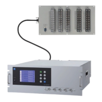
< Analog output > A/O connector
AO1+
AO1
-
AO2+
AO2
-
AO3+
AO3
-
AO4+
AO4
-
AO5+
AO5
-
AO6+
AO6
-
AO7+
AO7
-
AO8+
AO8
-
AO9+
AO9
-
AO10+
AO10
-
AO11+
AO11
-
AO12+
AO12
-
NC
Note) Display Ch number is same
as the AO number under
standard specifications.
D-sub 25-pin female
13 1
25 14
 Loading...