EasyManua.ls Logo

FujiFilm RYB751S3-VBC - Page 59

FujiFilm RYB751S3-VBC
252 pages
Print Icon
To Next Page IconTo Next Page
To Previous Page IconTo Previous Page
Loading...
WIRING
3
3-27
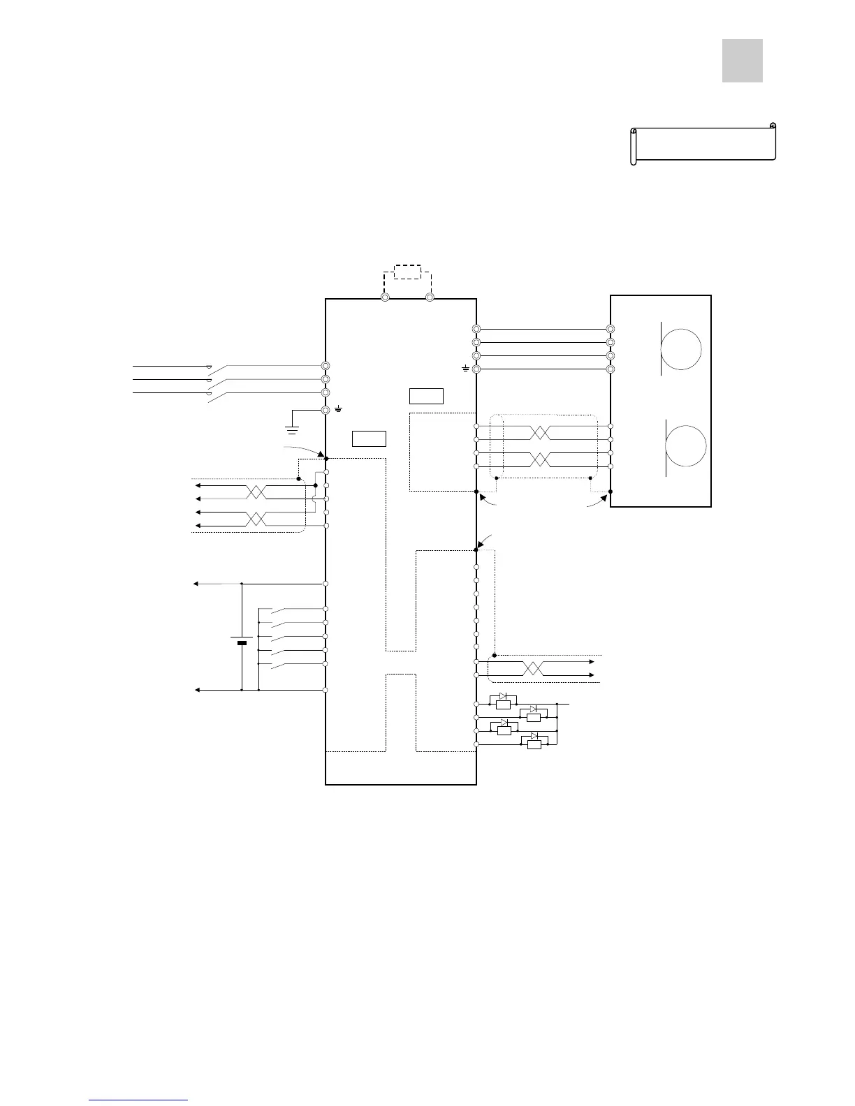
n Positioning module (NC1F-VP1)
Servo side
U
V
W
1 U
2 V
3 W
4 E
7 CA
8 *CA
21 *CB
20 CB
M
 1 P5
 2 M5
 5 SIG+
 6 SIG-
P5 1
M5 2
SIG+ 5
SIG- 6
PG
FZ 25
M5 26
L1
L2
L3
FFA 9
FFB 11
*FFB 12
FFZ 23
*FFZ 24
*FFA 10
CN1
CN1CN1
CN1
CN2
CN2CN2
CN2
1 P24
2 CONT1
5 CONT4
3 CONT2
6 CONT5
14 M24
4 CONT3
P24
OUT1 15
OUT2 16
RDY 17
PSET 18
P24
DB
19 PPI
P
⑤
⑥
M5 13
①
②
③
④
*1
*1 *1
⑦
M24
⑧
DC24V
*1
Servo amplifier
Commercial power
supply 3-phase 200V
External regenerative
resistor (Option)
Servomotor
(Without brake)
*1: Connect the shielding wires to the connector shell of CN1 and CN2. The connector shell is connected with the grounding terminal.
*2: Ground the shielding wire at both ends. (Connect it to the connector shell on the amplifier side, and connect it to the FG (ground) termin
on the pulse generator side.

Table of Contents