5
PARAMETERS
5-6
5-3) Basic settings
The basic setting parameters are described in the order of the parameter number.
Basic setting parameter #01 and #02
No. Name Setting range Initial value Change
01
Command pulse correction α
1 to 32767 (in 1 increments) 8 Always
02
Command pulse correction β
1 to 32767 (in 1 increments) 1 Always
These parameters are used to convert the travel distance per each command pulse into a unit quantity that
is used by the electronic gear.
Calculate in the following equation.
n Calculation formula for command pulse correction α and β
Reduce the fraction so that command pulse correction α and β become integers within 32767.
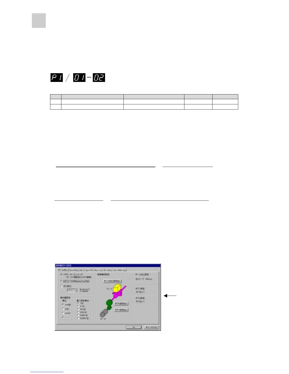
n Setting from PC loader (option)
Use the “α and β setting from mechanical configuration” button in the parameter editing screen of the
PC loader to automatically specify command pulse correction values α and β.
<α / β setting screen>
Data are automatically set by
simply entering the machine
specifications.
Because settings are given
for each component of the
machine, entry is simply.
(65536 pulses/rotation)
=
(Unit quantity)*
(Command pulse correction )
(Command pulse correction )
×
(Mechanical system travel distance per revolution of servomotor)
* "Unit quantity" is a value such as "1," "0.1," "0.01," and "0.001."
(65536 pulses/rotation)
x (Unit quantity)
(Command pulse correction )
(Command pulse correction )
(Mechanical system travel distance per revolution of servomotor)
=
α
β
α
β
 Loading...