PARAMETERS
5
5-7
Hence command pulse correction α becomes “8192” and command pulse correction β becomes “125.”
With the above settings, the mechanical system travel distance per each pulse in the pulse string
becomes 0.01 mm.
(65536 pulses/rotation)
=
(Unit quantity)
(Command pulse correction )
(Command pulse correction )
×
(Mechanical system travel distance per revolution
of servomotor)
α
β
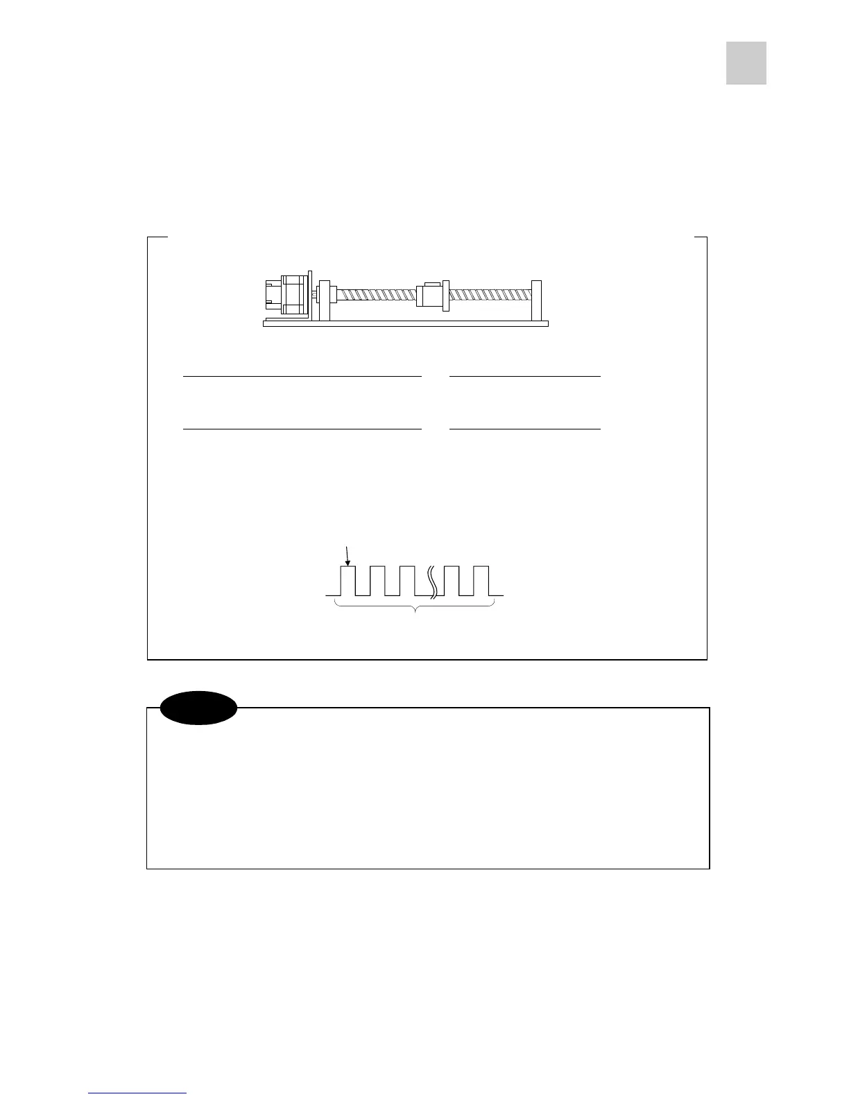
0.01 mm with each pulse
10 mm with 1000 pulses
(one full revolution of motor)
To couple 10-mm-lead screw to the output shaft of the servomotor with a setting unit of 1/100
The pi (π) included in the mechanical system travel distance per each revolution of the servomotor can
be approximated with “355 / 113.”
The number of output pulses has nothing to do with command pulse correction. According to the
setting of system setting parameter #17, two signals with phase-B-advanced 90-degree phase difference
are out
ut when the motor shaft rotates in the forward direction.
NOTE
(65536 pulses/rotation)
=
1/100
(Command pulse correction )
(Command pulse correction )
×
10 mm
α
β
 Loading...