Chapter 2 Components
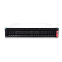
2.1 Controller Enclosure
ETERNUS DX80 S2/DX90 S2 Disk storage system User’s Guide -Installation-
Copyright 2013 FUJITSU LIMITED P3AM-4832-07ENZ0
33
● Part explanation
• LAN (RMT) port, LAN (MNT) port
These ports are RJ-45 connectors for LAN cables.
• Host interface (CA#0), host interface (CA#1)
Install host interfaces. For details, refer to "Host interfaces" (page 34)
.
• DI (OUT) port
This port is used to connect a controller enclosure to a drive enclosure with a QSFP cable.
• PWC port
This port is used to connect a power synchronization unit with an RS232C cable.
• LEDs
The states of LEDs are listed below.
Table 2.3 Status and meanings of each LED (controller)
LED name LED status Controller status
READY/FAULT
(green)
The controller is in normal status.
(amber)
• The controller is performing the initial setup after the power is
turned on.
• The controller is in error status.
(blinks amber)
MASTER
(green)
The controller is set as a Master CM.
UNIT ID
(blinks green)
• As ordered via ETERNUS Web GUI or ETERNUS CLI, the
installation location of the controller is identified.
• System Capacitor Unit (SCU) is charging.
CA FAULT
(amber)
The host interface is in error status.
LINK/FAULT
(green)
The link between the host interface port and the destination port
has been established.
(amber)
The host interface port is in error status.
DI (OUT) LINKUP
(green)
The link between the DI (OUT) port and the destination port has
been established.
ACT
(green)
The controller is sending or receiving data via the LAN port (for
operation management).
LINK
(green)
The link between the LAN port (for operation management) and
the destination has been established.
 Loading...