− 67/83 −
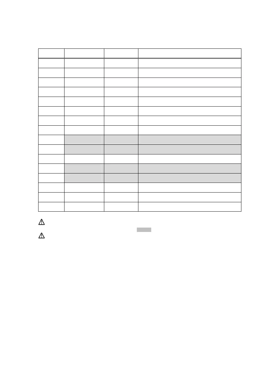
(2) Serial Interface Connector
Pin No. Signal Name Direction Signal Line Name
1
SG - Signal Ground
2 TXD Output Transmit Data
3 RXD Input Receive Data
4 RTS Output Request to Send
5 CTS Input Clear to Send
6 DSR Input Data Set Ready
7 SG - Signal Ground
8~12 N.C - No Connection
13 SG2 - +24V Ground
14 SG2 - +24V Ground
15~17 N.C - No Connection
18 +24V - Mechanical Drive Power
19 +24V - Mechanical Drive Power
20 DTR Output Data Terminal Ready
21~24 N.C - No Connection
25 INIT Input Forcible Reset Signal
Caution: When the power is supplied from the power connector, ensure
the pins shaded in grey are not connected.
Caution: Use a lock screw with an imperial thread on the connector.