3.3 Power Supply Requirements
C156-E228-02EN 3-15
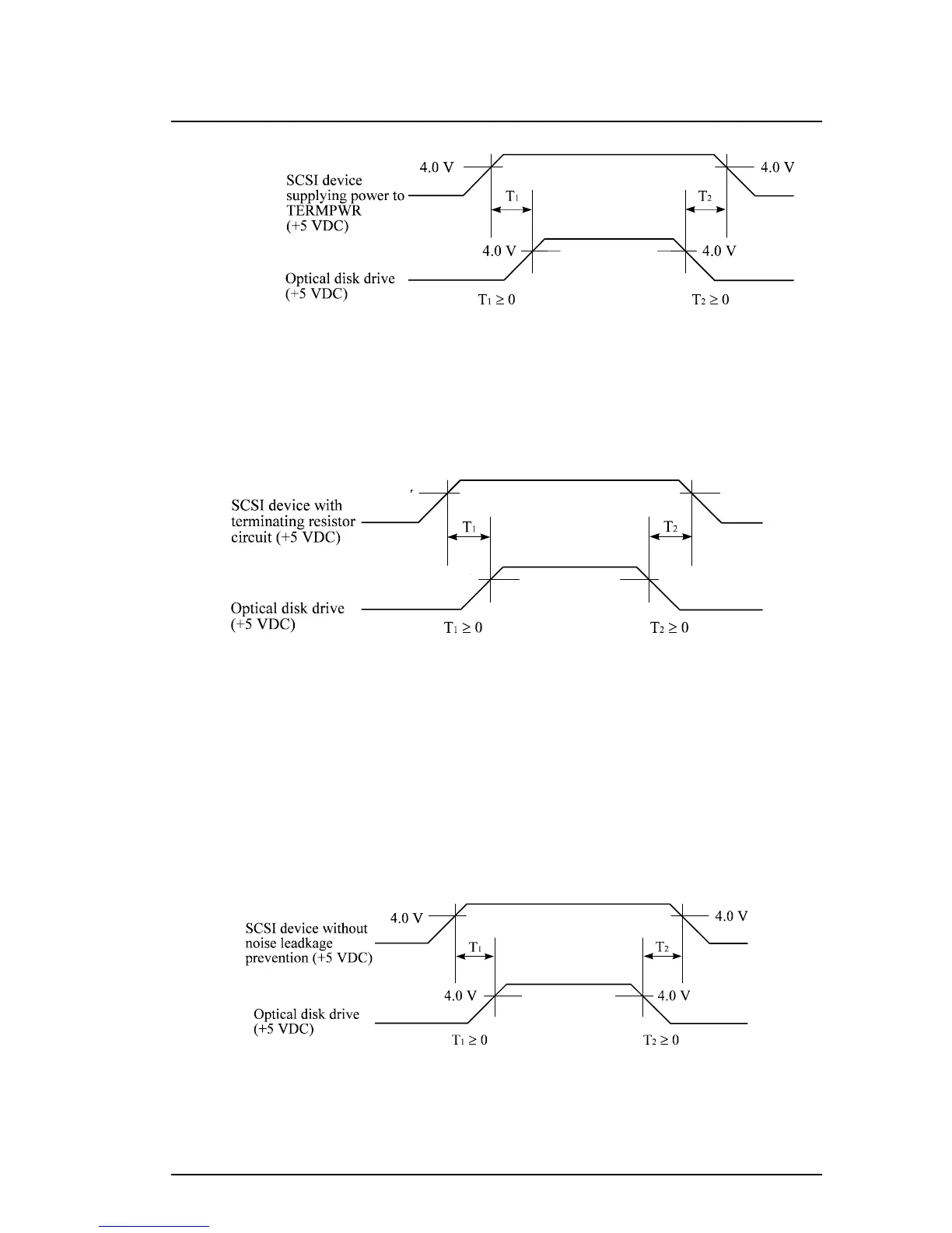
Figure 3.9 Power on/off sequence (1)
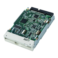
b) In a system which does not use the terminating resistor power supply signal
(TERMPWR) of the SCSI bus, the requirements for +5 VDC given in Figure
3.10 must be satisfied between the drive and the SCSI device with the
terminating resistor circuit.
Figure 3.10 Power on/off sequence (2)
c) Between the drive and other SCSI devices on the SCSI bus, the +5 VDC
power on/off sequence is as follows:
In a system with all its SCSI devices designed to prevent noise leakage to the
SCSI bus when the power is turned on or off, the power sequence does
not matter if the requirement in (a) or (b) is satisfied.
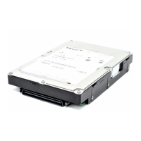
In a system containing an SCSI device which is not designed to prevent noise
leakage to the SCSI bus, the requirement given in Figure 3.11 must be
satisfied between the SCSI device and the drive.
Figure 3.11 Power on/off sequence (3)
0.5V
4.75V
0.5V
4.75V