Brocade 5450 Hardware Reference Manual 37
53-1001266-02
Interpreting LED activity
4
Interpreting LED activity
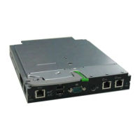
Each Embedded Switch Module uses the following external LEDs to indicate status. These LEDs are
shown in Figure 13.
FIGURE 13 LED Locations
TABLE 6 Key to Figure 13
Location Indicator Color Operation
1 ID blue This LED is controlled by ISMIC and the MMB. The Fabric
operating system (FOS) does not monitor or manage this
LED.
2module
health
green/amber This LED is controlled by ISMIC and the MMB. The Fabric
operating system (FOS) does not monitor or manage this
LED.
3module
status
green/amber Off:
Invalid; the switch is off.
Green:
No errors and all ports are ready for use.
Amber:
Steady: Boot-up state, ports offline, or in reset state.
Blinking (green/amber): One or more environmental ranges
are exceeded, or error log contains diagnostic error
messages.
Note: The LED might blink during testing.
4FC (external)
port status
green/amber Note: LED meanings are not valid during boot, diagnostics,
or POST.
Green:
Off (dark): No signal carrier or unlicensed.
Steady: Online normal active port but no port activity.
Flickering: normal active port (I/O activity).
Slow blink: Online but segmented.
Fast blink: Internal loopback.
Amber:
Steady: Signal present but not online.
Slow blink or flash: Disabled port (less than two second
interval).
Fast (rapid) blink or flash: Error or fault with port (less than
1/2 second interval).
 Loading...