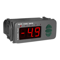
Identification of the discharge line on display:
Des1: Discharge 1
Des2: Discharge 2
Des3: Discharge 3
1
4
6
8
5
7
2
3
1
2
3
4
5
6
7
8
Out: Percentage of power referring to the
active outputs by the RCK-862 plus
Temp: It is the discharge value, used to
measure the subcooling
Pr es : It is pressure value read by the
discharge transducer
Setpoint: Displays the active pressure or
temperature setpoint value. It can be the main or
economy setpoint or resulting from the calculation
of the floating condensation logic
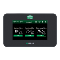
12.SUMMARY SCREEN
12.3. Discharge summary screen:
Displays the basic status of the enabled Discharge line.
To configure the Discharge lines, access the Main Menu Function Configuration Discharge. For more information see section 18. Main cc cc
Menu Function 1.1.3ddd
Setpoint: 300.0 psi
Pres: 330.0 psi
Temp: 50.0°C
Subcooling: 5.0°C
T.Ext.: 38.0/34.0°C
Req: 100% Out: 100%
Dis1
On
Eco
Pd
M
Req: Percentage of power required by the
system for the operation interval
T.Ext.: Represents the value of the
external temperature sensor (s) used in the
floating and adiabatic condensations. The value
on the left indicates the value of the dry bulb
temperature sensor (configured in menu
1.3.x). The value on the right represents the
wet bulb sensor (configured un Adiabatic
Condensation - 1.7.3.x). This information
will only be displayed if the sensors are
parametrized.
Subc o o l i n g: Calculation of subcooling
based on pressure, temperature, and type of
refrigerant settings. If the controller identifies the
suction that is operating in the trans critical part of
the refrigerant, the message PC will be displayed
13
 Loading...