16.AUXILIARY FUNCTIONS
16.6 Individual thermostats:
The RCK-862 plus allows you to configure up to 6 individual thermostats unrelated to the Rack’s main control. Each thermostat can be configured to
work in heating or cooling mode. In heating mode, the output is activated if the temperature value is lower than the (setpoint-hysteresis) and shuts off if
the temperature value is higher than the setpoint. In cooling mode, the output is activated if the temperature value is higher than (setpoint + hysteresis)
and turns off if the temperature value is lower than the setpoint.
Each thermostat has a defrost function, where you can determine a fixed interval between defrosts or select up to 6 independent times to start
defrosting. During defrost, the main output of the thermostat is shut off and the defrost output os activated until the time of Defrost duration
(1.7.6.x.15) has elapsed. The use of the defrost outlet is optional.
It is possible to synchronize the operation of one or more thermostats with a suction pressure switch. This feature causes the suction pressure switch is
linked to the thermostat in the parameter linked Pressure switch (1.7.6.x.7). The pressure switch will only enter Pump Down when all thermostats
connected to that suction are shut off.
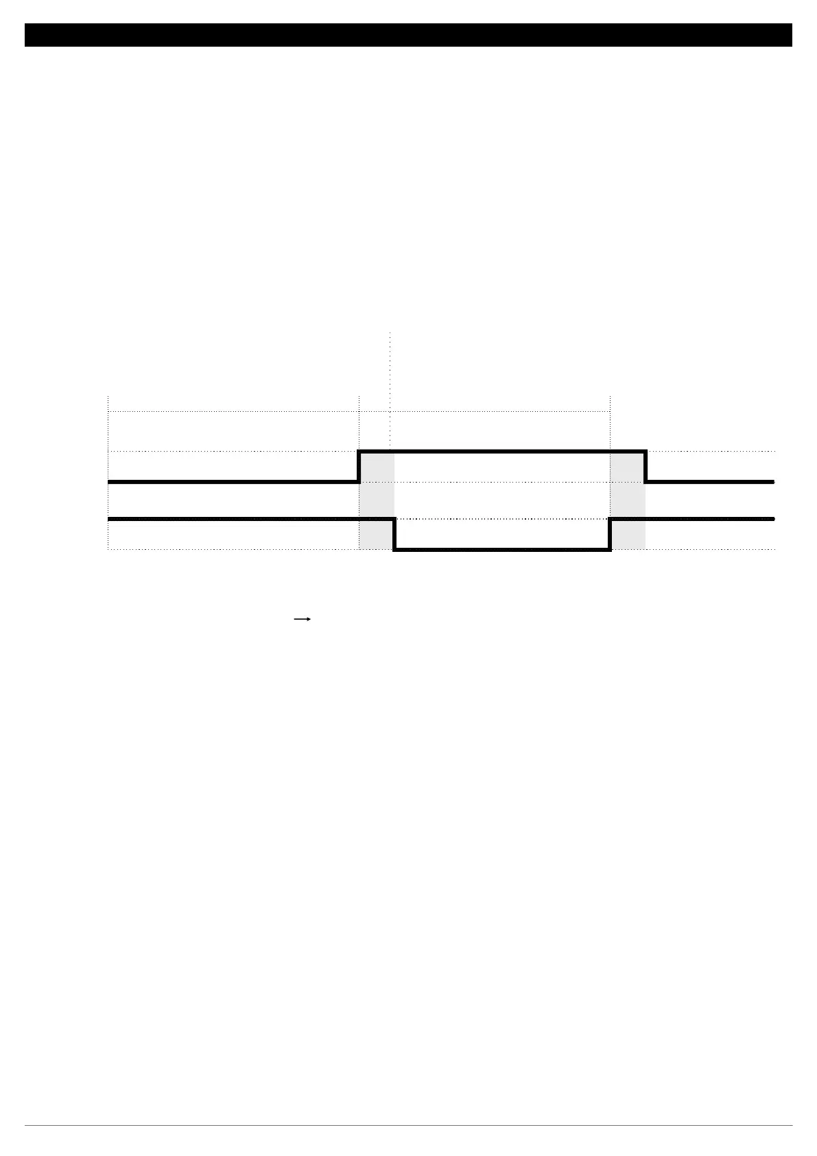
16.7 Outputs with rotation:
The RCK-862 plus allows you to configure up to 3 sets of outputs with a rotation function, for controlling pumps, for example.
In each set, it is possible to configure two digital outputs that operate alternately respecting the Time for rotation of the outputs (1.7.7.x.1) and the
transition time (1.7.7.x.2),which is the time that the two outputs remain on before making the change.
To configure a lack of flow digital input, the corresponding set of outputs must be selected in the menu (1.6.x.1) and the input function (1.6.x.2)
as Safety 1 for pump 1 flow sensor, Safety 2 for pump 2 flow sensor or Safety 3 for common flow sensor for both pumps.
Outlet sets 1, 2 and 3 operate with suctions 1, 2 and 3, respectively. The compressors come into operation only after the start of one of the pumps and are
switched off in the event of a lack of flow alarm in both pumps.
16.8 Control Status:
It allows configuring a digital output for indicating the operation of the controller. This output is only switched off in the event of a power failure and when
the control functions are switched off (Control Menu Control Status = Off).ddd
Output 2
Transition time
Rotation time Rotation time
Transition time
Output 1
36
 Loading...