16.AUXILIARY FUNCTIONS
16.5 Individual pressure switches:
The RCK-862 plus allows configuring up to 3 individual pressure switches disconnected from the Rack’s main control. On each pressure switch, it is
possible to associated a pressure sensor and up to 6 digital outputs with setpoint and independent hysteresis.
Each pressure switch can be configured to work in compression or descompression mode. In compression mode, the output is activated if the pressure
value is lower than the (setpoint-hysteresis) and shuts off if the pressure value is higher than the setpoint. In the decompression mode, the output is
activated if the pressure value is greater than (setpoint+hysteresis) and shuts off if the pressure value is lower than the setpoint.
Example:
1.7.5.x Individual pressure switch 1: with two outlets
1.7.5.x.1 Operating mode: Decompression
1.7.5.x.2 Pressure setpoint 1: 10,0 PSI
1.7.5.x.3 Pressure setpoint 2: 20,0 PSI
1.7.5.x.8 Pressure hysteresis 1: 5,0 PSI
1.7.5.x.9 Pressure hysteresis: 5,0 PSI
1.7.5.x.14 Pressure sensor: S1
1.7.5.x.15 Digital output address 1: O1
1.7.5.x.16 Digital output address 2: O2
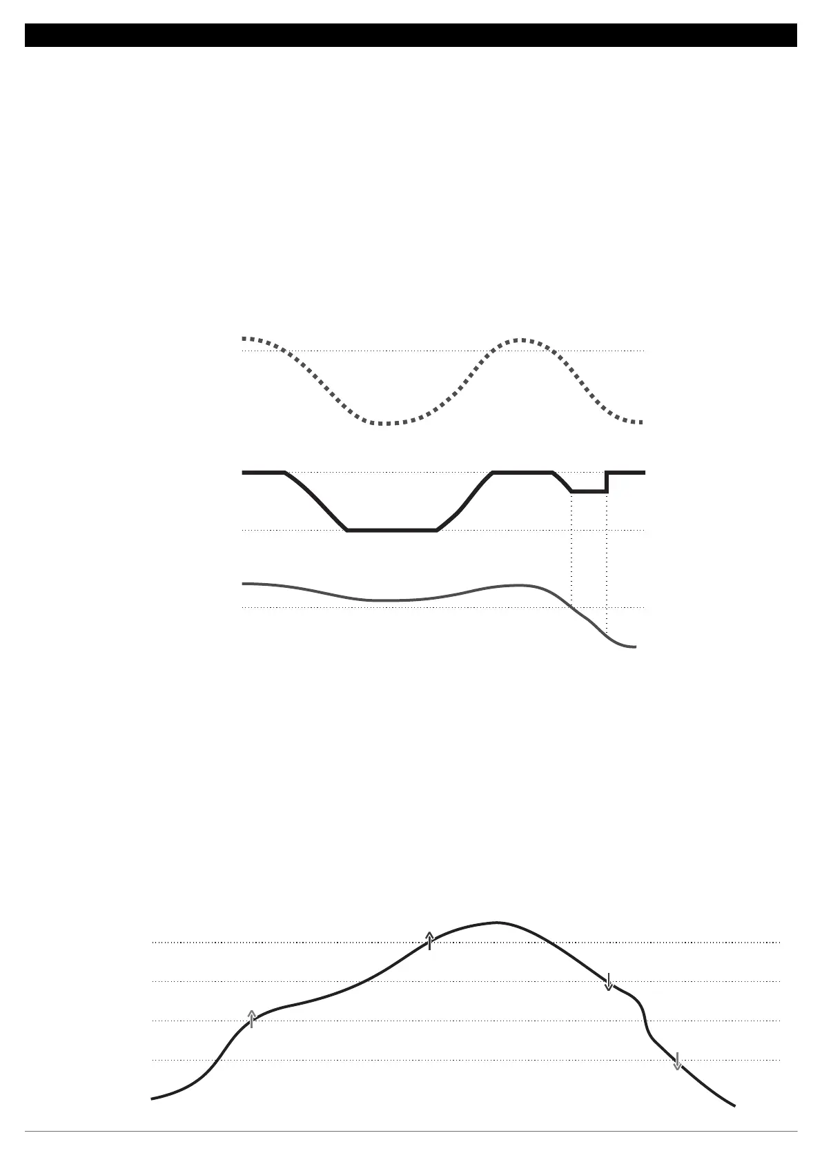
Fluctuation start
temperature
Safety value
Alarm value
Temperature
Discharge
setpoint
Min. Safety
setpoint
Setpoint
Subcooling
10
15
20
25
O1 = ON
O2 = ON
O1 = OFF
O2 = OFF
(psi)
16.4 Floating condensation:
The floating condensation logic can be used to lower the compressor discharge pressure and consequently reduce the compressor’s energy
consumption according to the air temperature value. To use the logic, a pressure sensor must be configured for the discharge, a temperature sensor for
measuring the external temperature and a temperature sensor for calculating the subcooling.
In the Floating condensation menu (1.7.4) you can access the essential parameters for the logic to work, such as the Temperature to start the
fluctuation (1.7.4.x.1), the minimum safety setpoint (1.7.4.x.2) and safety subcooling value (1.7.4.x.3).
This logic can be programmed to work only in a complying time interval (1.7.4.x.4 and 1.7.4.x.5) or by means of the command of an
auxiliary input (1.6.x.2).
When enabled, the logic goes into operation as soon as the temperature of the sensor that is measuring the external temperature is lower than the value
of the parameter Fluctuation start temperature (1.7.4.x.1). In this case, the discharge setpoint decreases proportionally as the external
temperature decreases, following the ratio of 1 to 1 degree until the maximum pressure variation. The controller uses the saturation data of the
refrigerant configured for the group belonging to the discharge pressure switch to perform the conversion of pressure to temperature.
Throughout the fluctuation if the calculated subcooling is equal to or better than the safety subcooling parameter (1.7.4.x.3), the control limits the
reduction of the discharge setpoint to the moment value. If the subcooling value rises by 1°C, then the floating condensation control returns to reducing
the discharge setpoint.
If at any time the subcooling decreases to the low subcooling alarm value, the logic is disabled and the discharge setpoint returns to the original value.
35
 Loading...