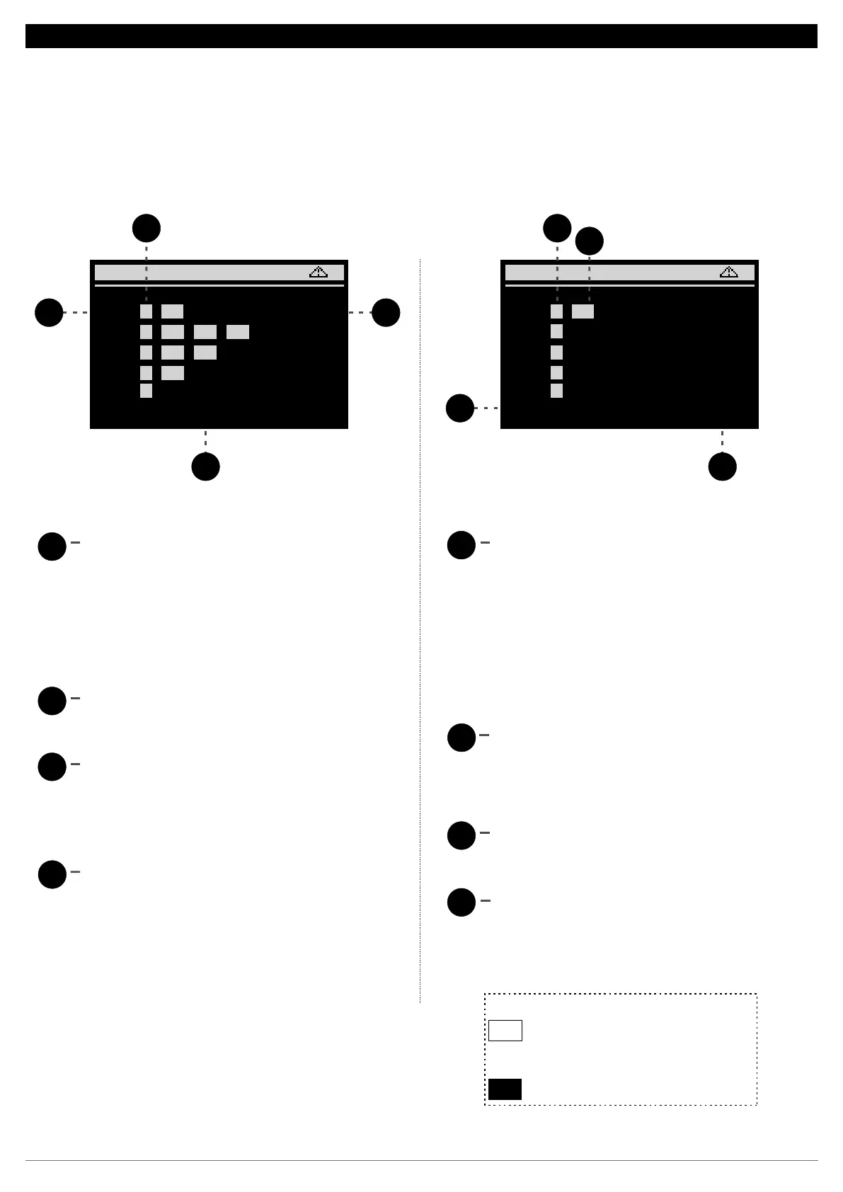
12.SUMMARY SCREEN
4 2
C1: = 100% A SS
C2: = 100% P U1 U2 U3
Suc1Suc1 On
Eco
Pd
M
C3: U3 = 75% P U1 U2
C4: U2 U3 = 50% P U1
C5: U1 U2 U3 = 25% P
C6: P U1 U2 U3 = 0%
3
1
4
Dis1
On
Eco
Pd
M
F1: = 100% A SS
F2: = 100% P U1 U2 U3
F3: = 100% P U1 U2 U3
F4: = 100% P U1 U2 U3
F5: = 100% P U1 U2 U3
F6: P = 0% U1 U2 U3
3
1
2
The letter P represents the activation of the
compressor’s main output. When digital output
P is indicated with a white background, it means
that is relay is activated.
T h e l e t t e r A s y m b o l i z e s t h e a n a l o g
(proportional) output-compressor configured as
an inverter. For values above 0% the letter A is
displayed with a white background
Lists all compressors enabled on the suction
pressure switch.
2
3
4
1
This value represents the percentage of the
power supplied by each compressor
Th e a ux il iary o ut pu ts (un loaders) a re
represented by the letter U.
The Start-Stop output of the compressor with
VCC-Analog modulation will be represented by
the letters SS
1
2
3
4
For fans with modulation, the SS symbol
represents the status of the Start-Stop output.
When this output is activated, it is represented with
a white background.
This value represents the percentage of the power
supplied by each fan
It lists all enabled fans of the discharge line, there
may be a total of six.
White background
Black background
Actuated output
Output configured but shutdown
The letter P represents the actuation of the fan
output. When digital output P is indicated with a
white background, it means that its relay is
activated.
For fans with inverter modulation (only the F1 fan
can be configured) the letter A symbiolizes the
value of the analog output. For values above 0%
the letter A will be shown with a white background.
12.4. Continuation of summary screens:
For each suction and discharge it has a summary screen where you can see how many outputs are connected and their respective status. After the
equal sign, you can see the percentage of the control outputs connected with each compressor and fan that are on. It can even monitor the capacity
control status (unloaders valves and inverter output).
14
 Loading...