5-2 FL14.10EA
The VCOM Adjustment should be
performed when replacing the Digital
Main CBA.
2. VCOM Adjustment
[TYPE A, B, D, F, G]
[TYPE A, B]
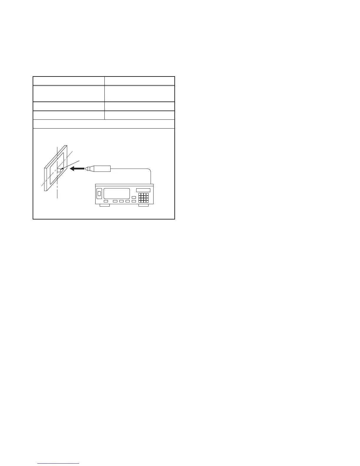
1. Set the color analyzer at the zero point calibration
and bring the optical receptor pointing at the
center of the LCD-Panel.
Note: The optical receptor must be set
perpendicularly to the LCD Panel surface.
2. Turn the power on.
Note: Execute the VCOM adjustment within 2
minutes after you turn the power on.
3. Enter the Service mode.
4. Press [2] button to select the VCOM adjustment.
5. Press [1] button to select the VCOM1 adjustment.
VCOM1 pattern signal (1 X 1 flicker) appears in
the screen.
6. Press [CHANNEL UP/DOWN] buttons on the
remote control unit so that the color analyzer value
becomes minimum.
7. To cancel or to exit from the VCOM Adjustment,
press [CH RETURN] or [PREV CH] button.
[TYPE D, F, G]
1. Set the color analyzer at the zero point calibration
and bring the optical receptor pointing at the
center of the LCD-Panel.
Note: The optical receptor must be set
perpendicular to the LCD Panel surface.
2. Turn the power on.
Note: Execute the VCOM adjustment within 2
minutes after you turn the power on.
3. Enter the service mode.
4. Press [2] button to select the VCOM adjustment.
5. Press [2] button to select the VCOM2 adjustment
VCOM2 pattern signal (1 X 2 flicker) appears in
the screen.
6. Press [CHANNEL UP/DOWN] buttons on the
remote control unit so that the color analyzer value
becomes minimum.
7. To cancel or to exit from the VCOM Adjustment,
press [CH RETURN] or [PREV CH] button.
Test Point Adj. Point
Screen
[CHANNEL UP/DOWN]
buttons
M. EQ. Spec.
Color analyzer See below
Figure
Color Analyzer
To avoid interference from ambient
light, this adjustment should be
performed in a dark room.
Perpendicularity