40
<Model Basic Setting Procedure>
Model Menu, and set the curve for each condition.
$WLQLWLDOVHWWLQJWKLVIXQFWLRQLVLQWKH,1+
VWDWH7RXVHLWVHWLWWRWKH21VWDWH
6HWWLQJH[DPSOH!
Call the mixing curve of each condition with the
condition select switch.
$FXUYHVHWWLQJH[DPSOHLVVKRZQEHORZ
ŏ3LWFKWR58'PL[LQJFXUYH1RUPDO
8VHWKHKRYHULQJV\VWHPDQGVHWWKLVFXUYHWR
PDWFKWDNHRIIDQGODQGLQJDQGYHUWLFDOFOLPEDW
DFRQVWDQWVSHHG
*For this curve, use the initial setting [EXP1] curve type.
ŏ3LWFKWR58'PL[LQJ,GOHXS
8VHWKLVFXUYHLQ
º
VWDOOWXUQORRSDQGUROOLQJ
VWDOOWXUQDQGDGMXVWLWVRWKHIXVHODJHLVIDFLQJ
VWUDLJKWDKHDGZKHQKHDGLQJLQWRWKHZLQG
*For this curve, [EXP1] curve type can be used and the entire
curve can be lowered with the [Offset] function.
ŏ3LWFKWR58'PL[LQJ+ROG
7KLVIXQFWLRQLVVHWVRWKDWWKHIXVHODJHLVIDFLQJ
VWUDLJKWDKHDGDWVWUDLJKWOLQHDXWRURWDWLRQ7KH
SLWFKRIWKHWDLOURWRUEHFRPHVQHDUO\
º
*For this curve, [EXP1] curve type can be used and the entire
curve can be lowered with the [Offset] function.
ŏ2WKHUVHWWLQJV
7KHPL[LQJULVHFKDUDFWHULVWLFDWSLWFKRSHUDWLRQ
FDQEHDGMXVWHG$QDFFHOHUDWLRQIXQFWLRQZKLFK
WHPSRUDULO\LQFUHDVHVDQGGHFUHDVHVWKHPL[LQJ
DPRXQWFDQEHVHW
9. Throttle hold setting
*If throttle hold is necessary, please refer to the THR HOLD
function, p.113.
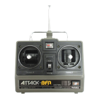
10. Throttle cut setting
Throttle cut provides an easy way to stop the
HQJLQHE\ÀLSSLQJDVZLWFKZLWKWKHWKURWWOHVWLFN
at idle. The action is not functional at high throttle
to avoid accidental dead sticks. The switch’s
location and direction must be chosen, as it defaults
WR18//
*With throttle stick at idle, adjust the cut position
until the engine consistently shuts off, but throttle
linkage is not binding.
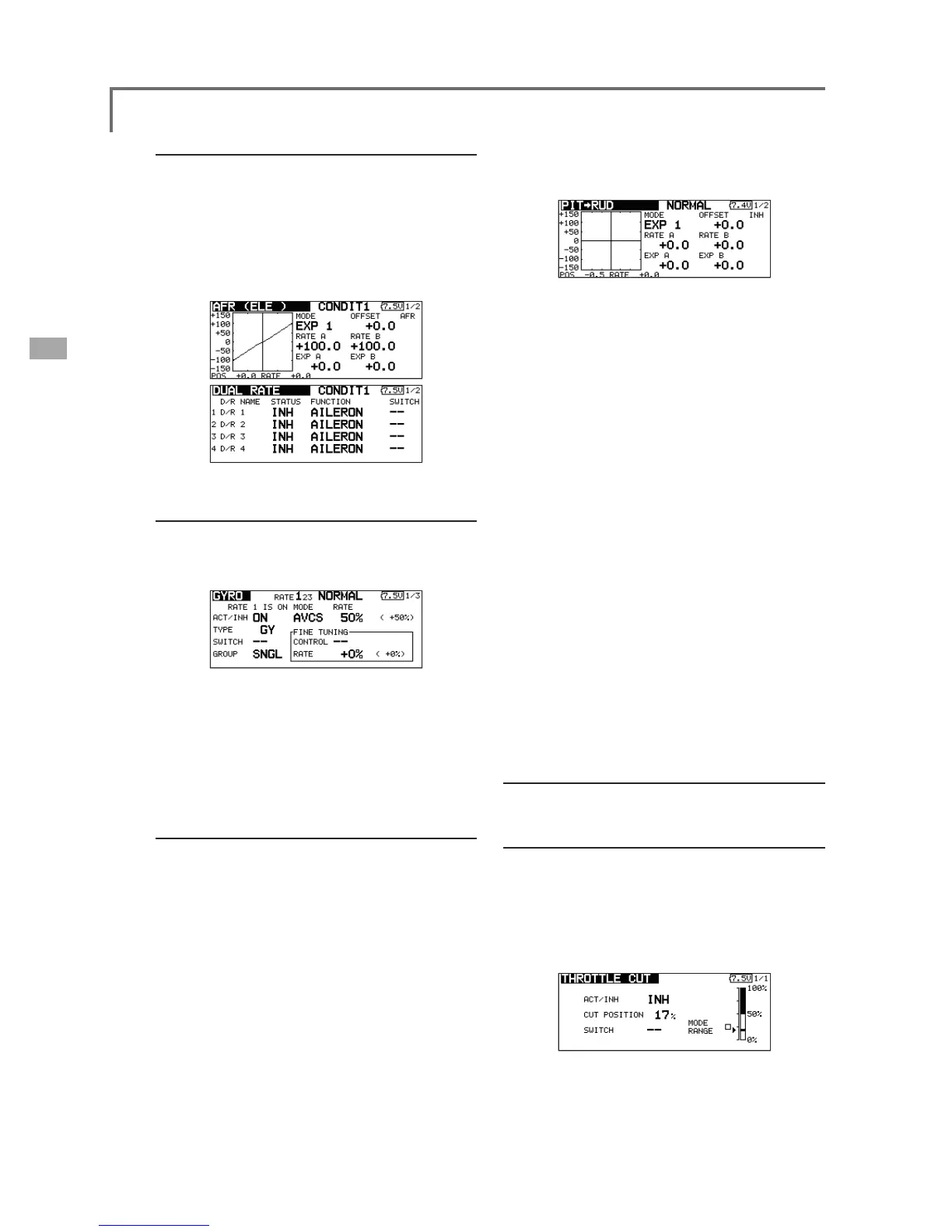
6. AFR (D/R)
AFR (D/R) function is used to adjust the throw and
operation curve of aileron, elevator and rudder for each
condition.
*For throttle and pitch curve settings, refer to the above-
mentioned "Throttle/Pitch curve setting"
7KLVLVQRUPDOO\XVHGDIWHU(QG3RLQWKDVGH¿QHGWKH
maximum throw directions.
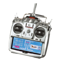
7. Gyro sensitivity and mode switching
The gyro sensitivity and mode switching
function is dedicated gyro mixing of the Model
Menu, and can be set for each condition.
ŏ1RUPDOFRQGLWLRQKRYHULQJ*\URVHQVLWLYLW\
PD[LPXP
ŏ,GOHXS,GOHXS7KURWWOHKROG*\UR
VHQVLWLYLW\PLQLPXP
ŏ+RZHYHUDWDXWRURWDWLRQRIDWDLOGULYHQ
KHOLFRSWHUWKLVIXQFWLRQPD\QRWKDYHDQ\
HIIHFWDWKLJKJ\URVHQVLWLYLW\
3LWFKWR58'PL[LQJVHWWLQJ
Note: When using a GY601, GY502, GY401,
or other heading hold gyro, this Pitch to RUD
mixing should not be used. The reaction
torque is corrected at the gyro side. When
operating the gyro in the AVCS mode, the
mixed signal will cause neutral deviation
symptoms and the gyro will not operate
normally.
Use this function when you want to suppress
the torque generated by the changes in the pitch
and speed of the main rotor during pitch operation.
Adjust it so that the nose does not swing in the
rudder direction. However, when using a heading
hold gyro like those shown below, do not use Pitch
to RUD mixing.
Call the Pitch to RUD mixing function from the