36
<Model Basic Setting Procedure>
MODEL BASIC SETTING PROCEDURE
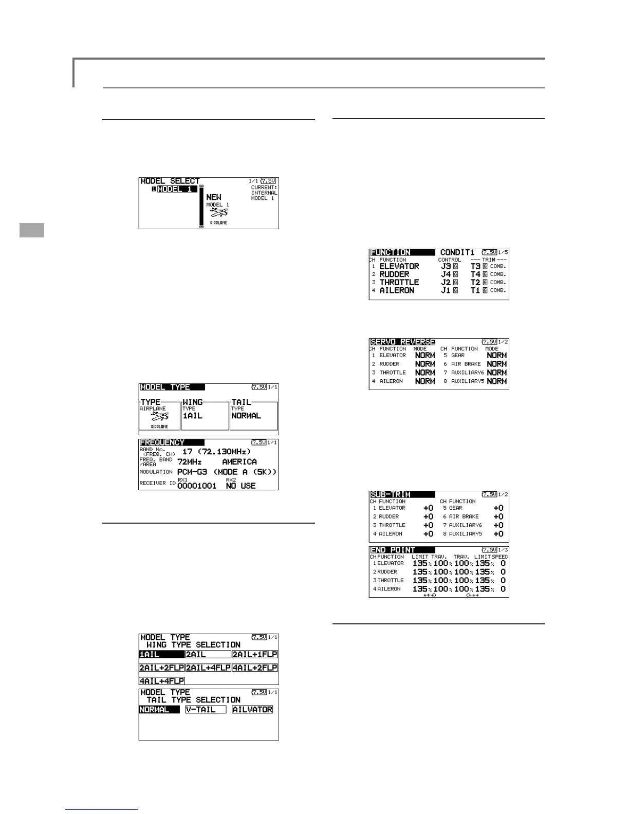
1. Model addition and call
Initial setting assigns 1 model to the T12FG
transmitter. The Model Select function of the
Linkage Menu is used to add models and to select
models which are already set.
The data for up to 30 models can be saved
to the transmitter. Data can also be saved to the
optional SD card.
The currently selected model name is displayed at
WKHWRSRIWKHVFUHHQ%HIRUHÀ\LQJDQGEHIRUHFKDQJLQJ
DQ\VHWWLQJVDOZD\VFRQ¿UPWKHPRGHOQDPH
When a new model is added, the Model type select
screen and Frequency/Modulation mode/Receiver ID
setup screen automatically appear. Please be aware
that the transmitter will stop transmitting when you
change the model.
2. Model type selection
Select the model type matched to the aircraft with
the Model Type select function of the Linkage Menu.
For an airplane, select the model type from among
the 2 types: airplane and glider. After the wing type is
selected the tail type select screen is displayed. Select
the tail type matched to the aircraft.
There are 13 wing types and 3 tail types for airplane
and glider.
Airplane/glider basic setting procedure
3. Fuselage linkage
Connect the ailerons, elevators, throttle, rudder,
etc. in accordance with the model's instruction
manual. For a description of the connection
method, see the Receiver and Servos Connection.
Note: The channel assignment of the T12FG is
different from that of our existing systems. Note
that even for the same "airplane model", when the
wing type and tail type are different, the channel
assignment may be different. (The channel assigned
to each function can be checked at the Function
menu of the Linkage Menu.)
ŏ,IWKHGLUHFWLRQRIWKHVHUYRLVLQFRUUHFWDGMXVW
WKHGLUHFWLRQZLWKWKH5HYHUVHIXQFWLRQRIWKH
/LQNDJH0HQX
ŏ$GMXVWWKHQHXWUDOSRVLWLRQDQGFRQWUROVXUIDFH
DQJOHZLWKWKHOLQNDJHDQGILQHWXQHWKHP
ZLWKWKH6XE7ULPDQG(QG3RLQWIXQFWLRQV
DQJOHDGMXVWPHQW7RSURWHFWWKHOLQNDJHD
OLPLWSRVLWLRQFDQDOVREHVHWZLWKWKH(QG3RLQW
IXQFWLRQ7KH(QG3RLQWIXQFWLRQFDQDGMXVWWKH
DPRXQWRIXSGRZQDQGOHIWULJKWPRYHPHQW
OLPLWDQGVHUYRVSHHGRIHDFKFKDQQHO
4. Throttle cut setting
Throttle cut can be performed with one touch by a
switch without changing the throttle trim position.
Set throttle cut with the Throttle Cut function of
the Linkage Menu. After activating the throttle cut
function and selecting the switch, adjust the throttle
position so that the carburetor becomes fully closed.
For safety, the throttle cut function operates the
throttle stick in the 1/3 or less (slow side) position.