31
Installation
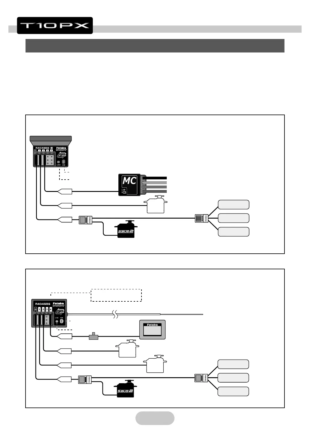
Receiver And Servo Connections
LED
Motor controller
Antenna
Link Switch
HUB
Steering servo
CH5~CH10 servo
S.BUS2 servo
S
CH2
CH1
Telemetry sensors
(Option)
Temperature
sensor
RPM sensor
Voltage sensor
CH5 to CH10 servo
*Only S.BUS2 servo
S
CH2
CH1
CH4
Battery
Throttle servo
(It connects with port which is not used.)
*When all the ports are used, connect
a battery using HUB or Y-harness.
Built-in antenna
*Receiver top is clean.
Out side Antenna
*Don't cut or bundle
the receiver
antenna wire.
Link Switch
LED
HUB
Steering servo
Telemetry sensors
(Option)
Temperature
sensor
RPM sensor
Voltage sensor
Installation When An Electronic Speed Control Is Used
Installation For Gas Powered Models
Connect the receiver and servos as shown below. Connect and install the receiver
and servos in accordance with
"
Installation Safety Precautions
"
on the next page.
The gure shown below is an example. The method of connecting the motor con-
troller to the motor and battery depends on the motor controller used. Purchase the
motor controller and servos separately. The receiver also depends on the set.
 Loading...