EasyManua.ls Logo

FUTABA T32MZ User Manual

FUTABA T32MZ
189 pages
To Next Page IconTo Next Page
Page #1 background imageLoading...
Page #1 background image
1M23Z06801
INSTRUCTION MANUAL

Other manuals for FUTABA T32MZ

Question and Answer IconNeed help?

Do you have a question about the FUTABA T32MZ and is the answer not in the manual?

FUTABA T32MZ Specifications

General IconGeneral
TypeTransmitter
Frequency2.4 GHz
Channels32
TelemetryYes
ModulationFHSS
SystemFASSTest/FHSS
BatteryLiPo 2S 7.4V
DisplayColor LCD

Summary

INSTRUCTION MANUAL

INTRODUCTION

Application, Export, and Modification Precautions

Guidelines for applying, exporting, and modifying the R/C system.

Compliance Information Statement (for U.S.A.)

FCC compliance statement for the radio control system.

Outside North America

Information relevant for users outside of North America.

Compliance Information Statement (for Canada)

Declaration of Conformity (for EU)

EU declaration of conformity for radio equipment.

Where to Fly

Information on finding model aircraft flying fields and clubs.

Precautions

Flying Precautions

Essential safety measures to follow during aircraft operation.

Battery and Charger Handling Precautions

microSD Card (Commercial Product) Handling Precautions

Storage and Disposal Precautions

Recommendations for storing and disposing of wireless equipment and batteries.

Other Precautions

Miscellaneous precautions for using the transmitter and accessories.

BEFORE USE

FEATURES

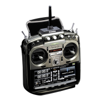
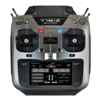
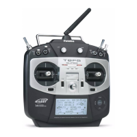
Overview of the key features and technologies of the T32MZ transmitter.

Contents and Technical Specifications

Cautions on handling antenna

Toggle switch

Digital trim

Touch Panel

Guide to operating the touch panel and its functions for data entry.

Stick Adjustment

Adjustment of Stick Lever Tension

How to adjust the tension of the stick levers for personalized feel.

Adjustment of Throttle Stick (Ratchet System)

Setting the ratchet system for the throttle stick for airplane or helicopter.

Battery exchange

Battery Charging

microSD Card (sold separately)

Read data from a PC

How to transfer music and image files from a PC to the microSD card.

Connector for trainer function (TRAINER)

S.BUS connector (S.I/F)

Connecting S.BUS servos or telemetry sensors.

Audio plug (PHONE)

Connecting headphones for audio playback or alerts.

Connector for battery charger (CHG)

Connecting the AC adapter for battery charging.

CRSF Protocol for TBS

Information on compatibility with the CRSF protocol for TBS devices.

Receiver nomenclature

Link/Mode Switch

Using the Link/Mode switch for CH mode selection.

Extra Voltage Connector

Connecting a voltage telemetry device to measure battery voltage.

Channel Modes

LED Indication

Understanding the LED indicators on the receiver for status information.

Systems (FASSTest ⇔ FASST) change method

Procedure for switching between FASSTest and FASST systems.

Servo (Option) · Toolbox · Receiver Switch

Receiver's Antenna Installation

Safety Precautions when you install receiver and servos

S.BUS Installation

S.BUS2 System

S.BUS device setting

Telemetry System

Slot No.

Understanding sensor classification by slot number and assignment.

Basic Operation

When turning on the power of the transmitter

Step-by-step guide for powering on the transmitter correctly.

How to stop the transmitter

Proper procedure for shutting down the transmitter to prevent data loss.

Home screen

Sub-Display

How to display telemetry information

Guide to accessing and displaying telemetry data on the transmitter.

Link procedure (T32MZ ↔ R7108SB)

Model ID

How to change the number of value

How to activate the function

Turning functions ON or OFF using the INH button.

How to return to home screen or go back one step

Navigating back to the previous screen or the home screen.

Switch selection

Display of operation status

Understanding status messages displayed when functions are operated.

Panel lock

Registration of the user's name

MODEL BASIC SETTING PROCEDURE

Airplane/glider basic setting procedure

Initial setup procedures for airplane and glider model types.

1. Model addition and call

Adding new models or selecting existing ones from memory.

2. Model type selection

Selecting the appropriate model type, wing type, and tail type for the aircraft.

3. Airplane linkage

Linking control surfaces like ailerons, elevators, and throttle according to the aircraft manual.

4. Throttle cut setting

5. Idle down setting

Setting the idle down function to lower engine idling speed with a switch.

Helicopter basic setting procedure

1. Model addition and call

Adding new models or selecting existing ones from memory.

2. Model type and swash type selection

Selecting helicopter model type and swash type for proper control.

6. Throttle hold setting

Pitch to RUD mixing setting

Mixing pitch and rudder to suppress nose movement during pitch operation.

10. Gyro sensitivity and mode switching

11. Throttle cut setting

Easy procedure to stop the engine using throttle cut function.

SYSTEM MENU

System Menu functions table

Overview of the functions available within the transmitter's system menu.

Trainer

Display

Date and Time

User Name

Switch

H/W Setting

Sound Volume

Player

S.BUS Servo

S.BUS Servo Description of function of each parameter

Detailed explanation of parameters for S.BUS servo functions.

Information

Unit System

Range Check

Linkage Menu

Linkage Menu functions table

A comprehensive table listing all functions within the Linkage Menu.

Servo Monitor

Model Select

Model Type

Picture

Sound

System Type

The example for choosing System Type

Examples of system types and corresponding compatible receivers.

Receiver link method in FASST and S-FHSS

Procedures for linking receivers using FASST and S-FHSS systems.

Function

SWAP

Trim change

Adjusting trim settings for each flight condition.

Sub-Trim

Servo Reverse

Fail Safe

End Point (ATV)

Throttle Cut

Idle Down

Swash Ring

Swash

Timer

Dial Monitor

Function Name

Telemetry

Audible telemetry information

A setup of each sensor display

Receiver Battery Display

Monitoring the receiver and external battery voltage levels.

Temperature Display

RPM Display

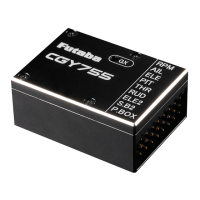
Monitoring engine RPM using the telemetry sensor.

Altitude Display

Variometer melody setting

Setting audible tones for aircraft ascent or descent rates.

Vario Melody Setting

GPS Display

GPS map display

Voltage Display

Current/Voltage/Capacity Display

Servo sensor Display

Airspeed Sensor Display

Sensor

Sensor unit reallocation

Sensor unit ID setting

Sensor Name

Telemetry Setting

Telemetry Alarm Duration and Repeat time

Warning

Data Reset

User Menu

Condition Hold

MODEL MENU (AIRPLANE/GLIDER FUNCTIONS)

Model Menu functions (AIRPLANE/GLIDER) table

Table of menus for airplane, glider, and EP glider model types.

AIL Differential

Flap Setting

AIL to Camber FLP

AIL to Brake FLP

AIL to RUD

Airbrake to ELE

RUD to AIL

Camber Mix

ELE to Camber

Camber FLP to ELE

Butterfly

Trim Mix 1/2

Airbrake

Gyro

V-tail

Ailevator

Winglet

Motor

RUD to ELE

Snap Roll

Multi Engine

Acceleration

MODEL MENU (HELICOPTER)

Model Menu (Helicopter Functions) table

Table of functions available in the Helicopter Model Menu.

Condition Hold function ON/OFF button

Controlling engine speed during flight adjustments to prevent dangerous racing.

PIT Curve/Pitch Trim

Hovering pitch trim

High Pitch/Low Pitch Trim

Adjusting pitch servo trim for high and low side operations.

THR Curve/Throttle Hover trim

Acceleration Mixing

Throttle Hold

Swash Mixing

Throttle Mixing

PIT to Needle Mixing

PIT to RUD Mixing (Revolution Mixing)

Gyro Mixing

Governor Mixing

Throttle Limiter

COMMON OPERATIONS USED IN FUNCTION SETUP SCREEN

Operations related to flight conditions

Managing flight conditions by group or single mode switching.

Operations related to VR tuning

Fine-tuning mixing rates using VR controls.

Servo speed setting (1)

Servo speed setting (2) (Prog. Mix only)

Setting servo speed for programmable mixing (slave/master) operations.

Curve setting operation

Linear curve adjustment

EXP1 curve adjustment

VTR curve adjustment

Adjusting VTR curves for engine control and rudder angle.

Line and spline curve adjustment

Switch selection method

Logic switch

Switch selection

Operation modes

UPDATING

Updating procedure

Step-by-step guide for updating the transmitter firmware via microSD card.

T18MZ (WC) → T32MZ MODEL DATA CONVERSION

Related product manuals