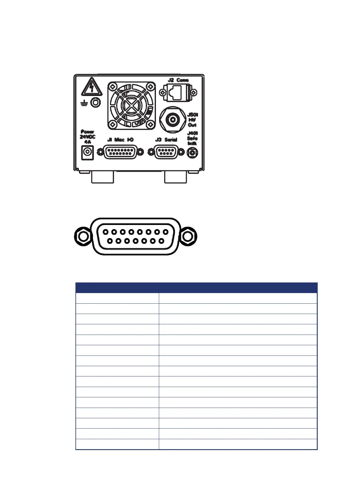
8. Back panel operation
Figure 49. Back panel view
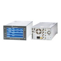
8.1. Remote hardware option (J1)
Figure 50. Remote hardware
The SPCe can be controlled by using the miscellaneous I/O 15-pin sub-d
connector.
Pin number Function
1 Setpoint relay common
2 Setpoint relay NC
3 GND
4 GND
5 -14 V
6 +14 V
7 +5 V
8 Remote HV Enable (3.3–12 V)
9 Setpoint relay NO
10 +14 V
11 Setpoint logic output
12 Output current monitor
13 HV enable monitor
14 Output voltage monitor
15 +14 V
04/2021 - ©Gamma
Page 34900026_F
900026_F - Back panel operation