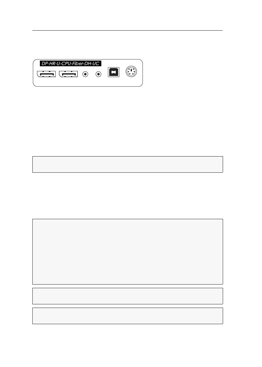
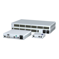
Target module »DP-HR-U-CPU-Fiber-DH-UC«
73 · Target and user modules (DP-HR-U)
Installation
Connecting the target computer
DP CPU 1: Use one of the supplied video cables to connect the computer’s first Display
Port video output to this interface.
DP CPU 2: Use one of the supplied video cables to connect the computer’s second Dis-
play Port video output to this interface.
Line In: Use one of the supplied audio cables to connect the computer’s Line Out
interface to this interface.
Line Out: Use one of the supplied audio cables to connect the computer’s Line In inter-
face to this interface.
USB K/M: Use the USB device cable to connect one of the computer’s USB interfaces
to this interface.
PS/2 Keyb.: Use an optional PS/2 cable to connect the computer’s PS/2 keyboard
interface to this interface.
Connections to the matrix switches
NOTE:
Keyboard and mouse signals can be transmitted to the computer using either
the PS/2 interfaces or the USB interface.
The devices use components with laser technology which comply with laser
class
1.
They meet the requirements in accordance to EN 60825-1:2014 as well as
U.S. CFR 1040.10 and 1040.11.
Mind the following instructions when dealing with laser beams:
Avoid direct eye exposure to beam on page 3
Always connect optical connections or cover them with protection caps on page 3
Only use G&D certified transmission modules on page 3
NOTE:
Use optical fibres with LC plugs to connect the devices. The cables are
available as accessories.
IMPORTANT:
For each matrix switch, connect only one Trans. interface of the tar-
get module!
PS/2 Keyb.
USB K/M
Line In
Line Out
DP CPU 1 DP CPU 2