Page 26
D1 & D2
These terminals are digicom outputs that are fully programmable by the engineer (see
Programmable Options Description for more details). The outputs are open collector
and have a maximum current sink of 50mA*
1
*
2
. On systems only using two channels
or systems using the ProDigi or Modem D1 & D2 are free for other uses.
Note: The start polarity is of the Digicom port is programmable by the
engineer.
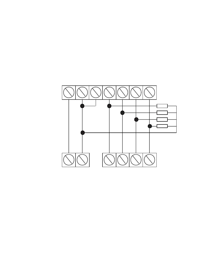
Fig. 15 Typical Digicom Wiring
Notes: D1 should be programmed for FIRE (Chan1)
D2 should be programmed for OPEN/CLOSE (Chan4)
Program Digicom Type to NORMAL
6K8 resistors provide Pull-Up for open collector outputs
When ordering STU chips Pin 4 must not be inverted as this is catered
for by the control panel.
*
1
No attempt should be made to exceed the stated current and the 1 Amp
maximum current draw from the control panel must be taken into consideration.
*
2
Some Digicoms may require a 6K8 pull-up resistor fitting between this output
and 12V
 Loading...