Page 27
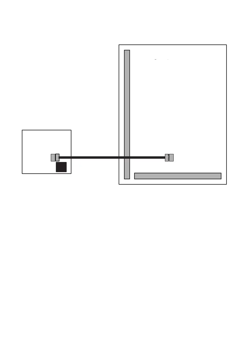
Fig. 16 ProDigi or GardTec Modem Wiring.
Note: Modem will give 8 channels and leave D1, D2 & D3 (PA term) free for
other uses
For a ProDigi program Digicom Type to Gardiner
For Modem Mod+FF or MOD+PID
Remove link from 12V & Line Fault Terminals before connecting
ProDigi/Modem
Both the ProDigi and GardTec Modem can be programmed direct from the
GardTec 872 control panel
Modem Patch Lead
If the GardTec Modem patch lead is to be used for direct connection to a PC or Lap-
Top It should be connected to SK3. The factory fitted link between 12V & Line Fault
must be removed. Full instructions on use of the GardTec Modem Patch lead are
supplied with the unit.
GardTec 872
Main PCB
If the GardTec Modem is used
basic system configuration is
available by defaulting the system
using 5, 5, YES, NO. Further
details are given in the GardTec
Modem manual.
GardTec 872
Wiring Connections
Modem Patch Lead if
direct connection to PC
is required.
 Loading...