Page 29
RKP 12V
This terminal provides the +12V supply for the keypads and ACE units (see Keypad
Wiring for more detail). A maximum current draw of 0.5Amp*
1
is available from this
terminal.
RKP 0V
This terminal is the 0V supply for the keypads and ACE units (see Keypad Wiring for
more detail).
CLK (for fault finding the voltage on this terminal should be approx 5V )
This terminal is the Clock connection for the keypads and ACE units (see Keypad
Wiring for more detail).
DATA A (for fault finding the voltage on this terminal should be approx 8V )
This terminal is the Data A connection for the keypads and ACE units (see Keypad
Wiring for more detail).
DATA B (for fault finding the voltage on this terminal should be approx 6V )
This terminal is the Data B connection for the keypads and ACE units (see Keypad
Wiring for more detail).
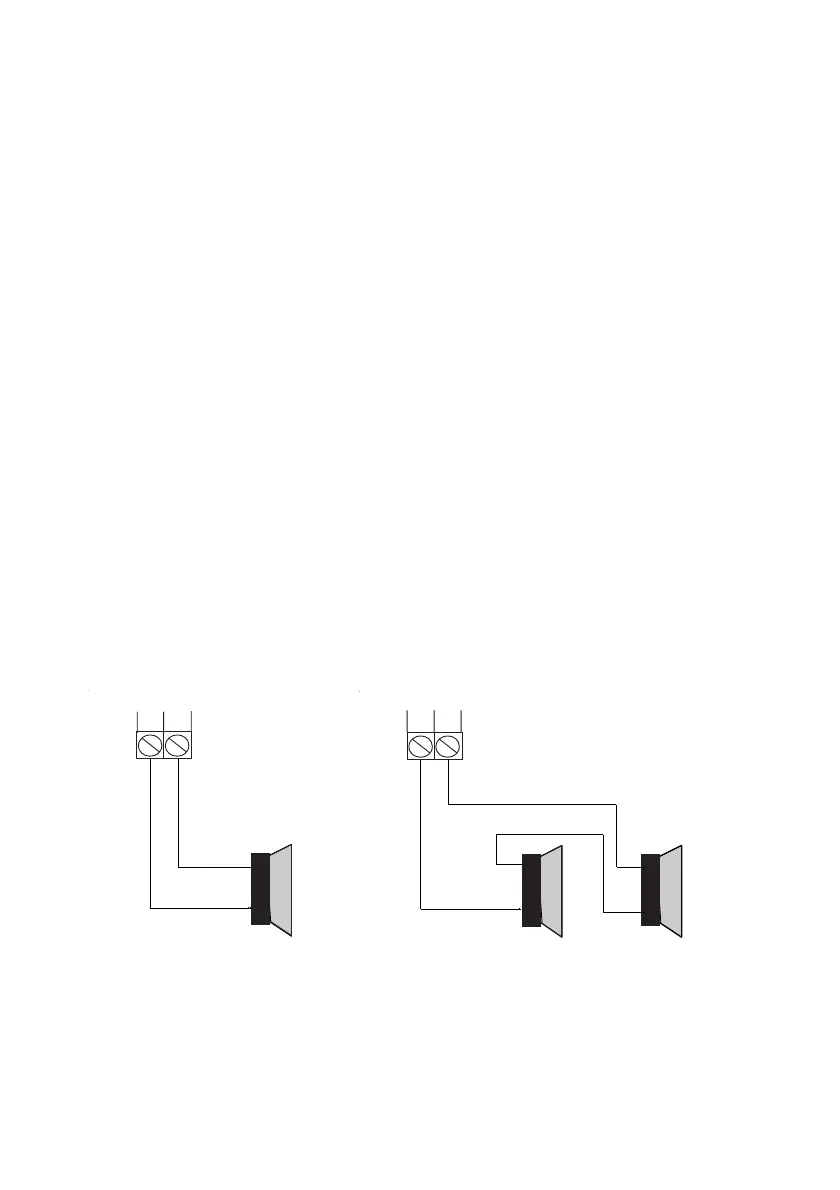
SPKR & SP+
These terminals are connected to any extension speakers (min impedance 16 Ohm)
that are fitted. The SP+ is the common and SPKR is the output of the amplifier driver.
The SPKR terminal is also connected to the SPKR (speaker terminal) on the RKP(s).
The current drawn by any extension speakers needs to be calculated in the total
system current. The current drawn by a 16 Ohm speaker would typically be 300mA.
Fig. 17 Single Speaker Fig. 18 Twin Speakers (wired in series)
Note: Minimum speaker impedance is 16 Ohm
*
1
No attempt should be made to exceed the stated current and the 1 Amp
maximum current draw from the control panel must be taken into consideration..
 Loading...