CHAPTER 1-Introduction
Pinouts
DS2000-IFR Installation and Maintenance Guide
1-10
* Fixed DCE with RxD, CTS, DSR and DCD as outputs.
* Fixed DCE with RxD, CTS, DSR and DCD as outputs.
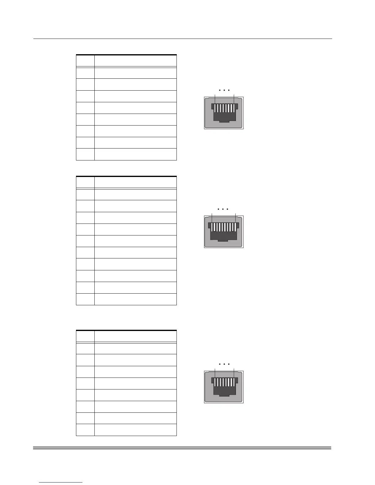
Table 1-9. W1 and W2 T1/E1 Ports - RJ48
Pin Signal
1 T1 Receive +
2 R1 Receive -
3 Shield
4 T Transmit +
5RTransmit-
6 Shield
7NotUsed
8NotUsed
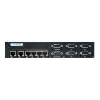
Table 1-10. S0 (Sync/Async)* - RJ69 (ten pin RJ45)
Pin Signal
1TxClock
2 Data Carrier Detect (DCD)
3 Receive Data (RxD)
4 Transmit Data (TxD)
5 Data Terminal Ready (DTR)
6 Signal Ground (SGND)
7 Data Set Ready (DSR)
8 Request To Send (RTS)
9 Clear To Send (CTS)
10 Rx Clock
Table 1-11. CON (console) Port 6* - RJ45
Pin Signal
1 Data Carrier Detect (DCD)
2 Receive Data (RxD)
3 Transmit Data (TxD)
4 Data Terminal Ready (DTR)
5 Signal Ground (SGND)
6 Data Set Ready (DSR)
7 Request To Send (RTS)
8 Clear To Send (CTS)
Pin 8Pin 1
Pin 8Pin 1
Pin 10Pin 1
Pin 8Pin 1 Pin 8Pin 1