SERVICE WORK ON THE CHASSIS 13
47
F02179-11
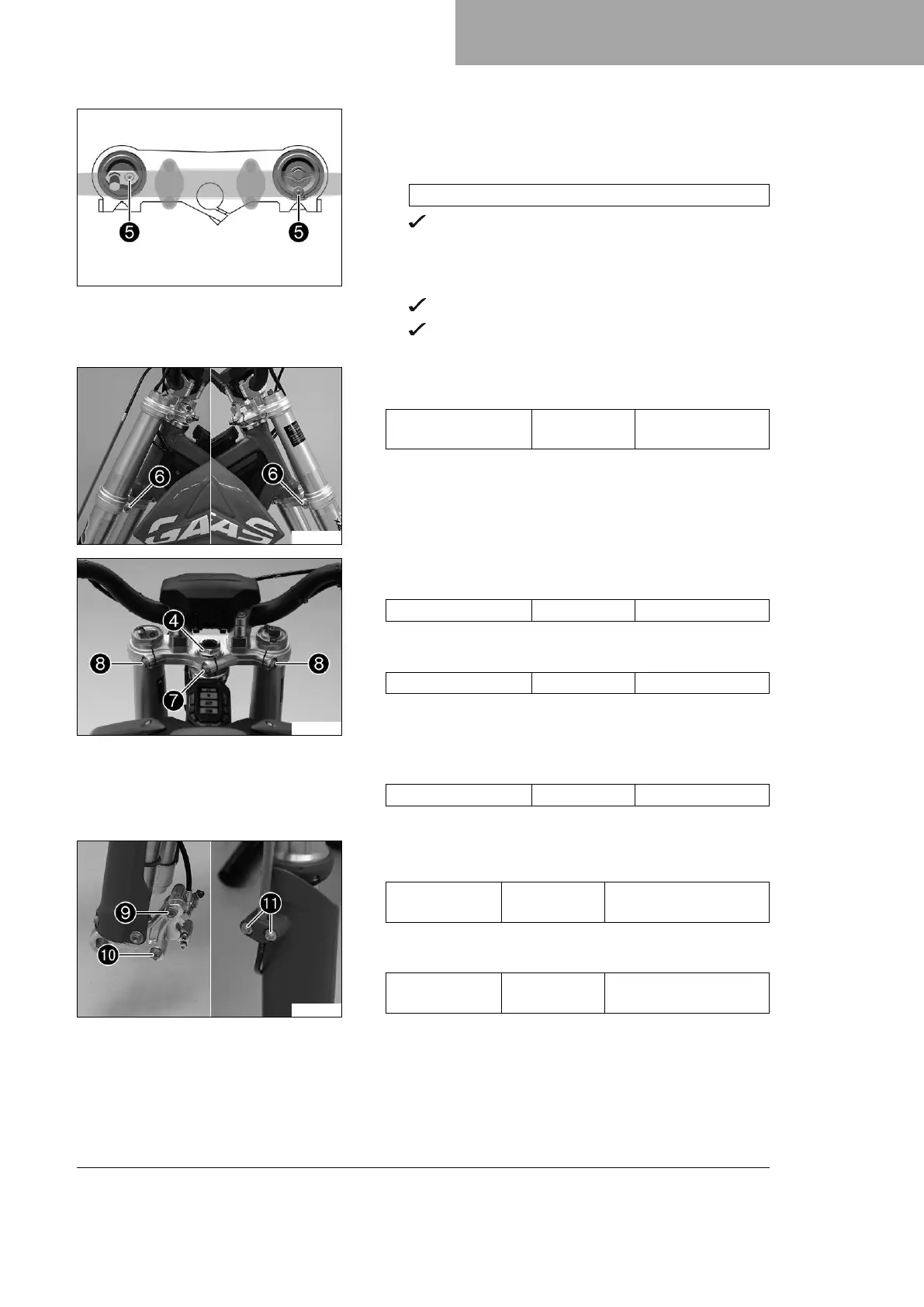
Condition
Individual installation position
– Position the fork legs.
Guideline
Observe the position determined during removal.
Bleeder screws
5
are positioned toward the rear.
Condition
Standard installation position
– Position the fork legs.
Bleeder screws
5
are positioned toward the rear.
The second milled groove (from the top) is flush with the
upper edge of the upper triple clamp.
M01862-10
–
Tighten screws
6
.
Guideline
Screw, bottom triple
clamp
M8 15 Nm (11.1 lbf ft)
M01845-10
–
Tighten nut
4
.
Guideline
Nut, steering head M20x1.5 10 Nm (7.4 lbf ft)
–
Tighten screw
7
.
Guideline
Screw, top triple clamp M8 20 Nm (14.8 lbf ft)
– Using a plastic hammer, tap lightly on the upper triple clamp to
avoid stresses.
–
Tighten screws
8
.
Guideline
Screw, top triple clamp M8 20 Nm (14.8 lbf ft)
– Fix the magnetic switch cable to the handlebar with a new cable tie.
M01843-11
–
Position the brake caliper, mount screw
9
, and tighten.
Guideline
Screw, front
brake caliper
M8x60 20 Nm (14.8 lbf ft)
Loctite
®
243™
–
Mount and tighten screw
bk
.
Guideline
Screw, front
brake caliper
M8x40 20 Nm (14.8 lbf ft)
Loctite
®
243™
– Position the brake line and the clamp. Mount and tighten
screws
bl
.
 Loading...