CHAPTER 6: SETPOINTS S2 SYSTEM SETUP
345 TRANSFORMER PROTECTION SYSTEM – INSTRUCTION MANUAL 6–25
Thus, for any load, the Winding 2 CT secondary current is higher (per unit) than the
Winding 1 CT secondary current. The mismatch factor is 1658.6 / 1500 = 1.1057.
The 345 relay calculates the magnitude correction factor for Winding 2 as follows:
Eq. 2
The 345 calculates and automatically corrects the CT mismatch to a maximum mismatch
factor of 16.
Hence, the measured currents from winding 2 will be automatically compensated by the
relay applying the correction factor of 0.904. The currents from winding 1 are not
multiplied by any correction factor, as they are always used by the relay as a magnitude
reference.
Based on 100% transformer loading (5MVA), the measured winding currents are:
Winding 1 CT: measured
Eq. 3
- winding 1 nominal current
Winding 2 CT: measured
Eq. 4
- winding 2 nominal current
Based on 100% transformer loading, the compensated currents expressed in times CT (w1)
as a reference and used by the percent differential protection will be as shown:
Eq. 5
Eq. 6
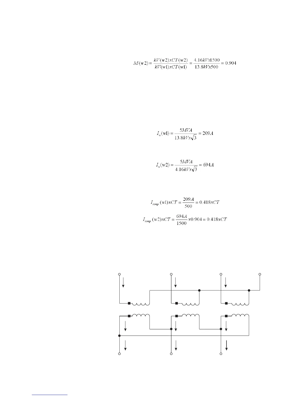
PHASE SHIFT COMPENSATION
The source phase sequence must be stated when describing the winding phase
relationships since these relationships change when the phase sequence changes. The
example below shows why this happens, using a transformer described in IEC
nomenclature as “Yd1” or in GE Multilin nomenclature as “Y/d30.”
Figure 6-12: Example transformer
897716A1.CDR
A
I
A
I'
a
BCN
abc
I
B
I
C
I'
b
I'
c
I=
a
I '–I'
ac
I=
b
I '–I '
ba
I=
c
I'–I '
cb