6–26 345 TRANSFORMER PROTECTION SYSTEM – INSTRUCTION MANUAL
S2 SYSTEM SETUP CHAPTER 6: SETPOINTS
The above figure shows the physical connections within the transformer that produce a
phase angle in the delta winding lagging the respective wye winding by 30°. The winding
currents are also identified. Note that the total current out of the delta winding is described
by an equation. Now assume that a source, with a sequence of ABC, is connected to
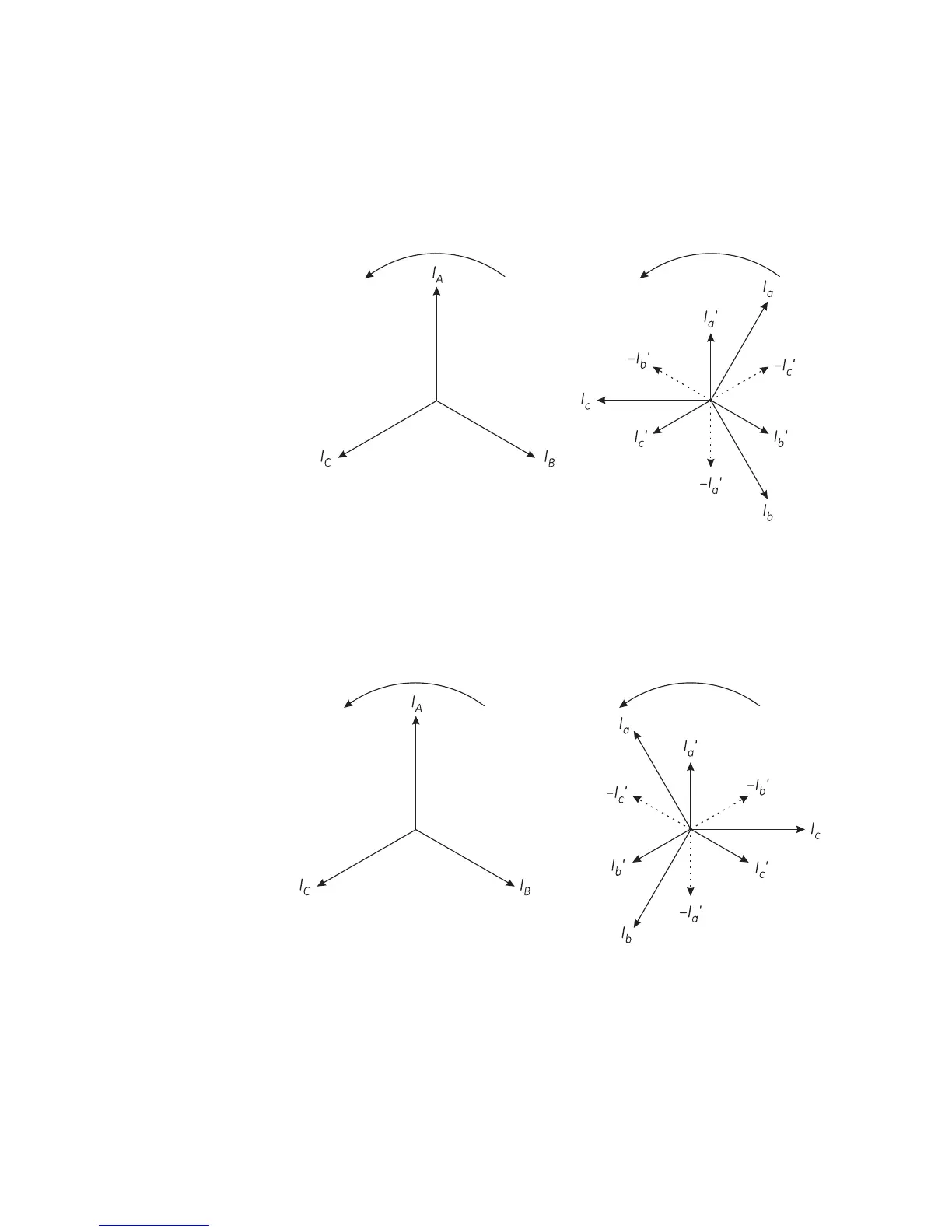
transformer terminals ABC, respectively. The currents that would be present for a balanced
load are shown below.
Figure 6-13: Phasors for ABC sequence
Note that the delta winding currents lag the wye winding currents by 30°, which is in
agreement with the transformer nameplate.
Now assume that a source, with a sequence of ACB is connected to transformer terminals
A, C, B respectively. The currents that would be present for a balanced load are shown
below:
Figure 6-14: Phasors for ACB sequence
Note that the delta winding currents leads the wye winding currents by 30°, (which is a
type Yd11 in IEC nomenclature and a type Y/d330 in GE Multilin nomenclature) which is in
disagreement with the transformer nameplate. This is because the physical connections
and hence the equations used to calculate current for the delta winding have not changed.
The transformer nameplate phase relationship information is only correct for a stated
phase sequence.