CHAPTER 6: SETPOINTS S2 SYSTEM SETUP
345 TRANSFORMER PROTECTION SYSTEM – INSTRUCTION MANUAL 6–27
It may be suggested that for the ACB sequence the phase relationship can be returned to
that shown on the transformer nameplate by connecting source phases A, B and C to
transformer terminals A, C, and B respectively. This will restore the nameplate phase shifts
but will cause incorrect identification of phases B and C within the relay, and is therefore
not recommended.
All information presented in this manual is based on connecting the relay phase A, B and C
terminals to the power system phases A, B and C respectively. The transformer types and
phase relationships presented are for a system phase sequence of ABC, in accordance
with the standards for power transformers. Users with a system phase sequence of ACB
must determine the transformer type for this sequence.
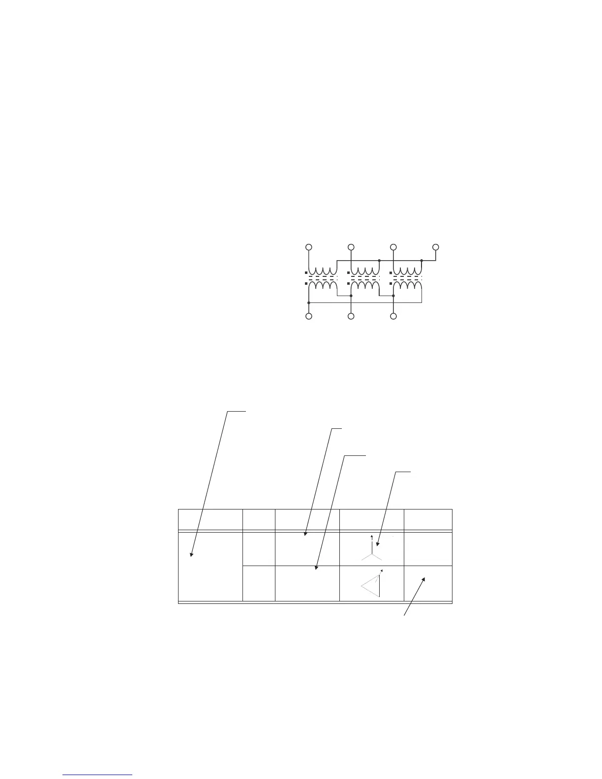
The following diagram shows the internal connections of the Y/d30? transformer from our
example:
The 345 performs this phase angle correction internally based on the following setpoint.
Set
S2 SYSTEM SETUP > TRANSFORMER > TRANSFORMER TYPE to “Y/d30°”.
The 345 supports all standard two-winding transformer types. Each transformer type from
the Transformer Types table below provides the following information:
As shown in the “Y/d30°” entry of the transformer types table, the 30° lag of the Delta
results into 0° phase shift applied to its currents (Delta –phase reference), and 30° phase
angle correction (phase shift) applied to the winding 1 currents (Wye winding). These angle
corrections are described in the table as Phase shift.
WINDING 1 (WYE)
WINDING 2 (DELTA)
abc
AB
C
N
897721A1.CDR
Wdg.
Y/d30°
1 30° lag
20°
transformer type notation as it appears on the display
winding connection (wye, delta, or zig-zag)
and ground CT assignment
angle by which a winding lags winding 1
diagrams showing the phase
relationships of voltage phasors,
where (the arrow sign)
indicates the reference phase
phase angle correction (or phase shift)
that is initially performed to calculate
differential currents
Transformer type
Connection
Voltage
phasors
Phase
shift
WYE
(gnd 1/2)
DELTA
30° Lag