CHAPTER 6: SETPOINTS S2 SYSTEM SETUP
345 TRANSFORMER PROTECTION SYSTEM – INSTRUCTION MANUAL 6–31
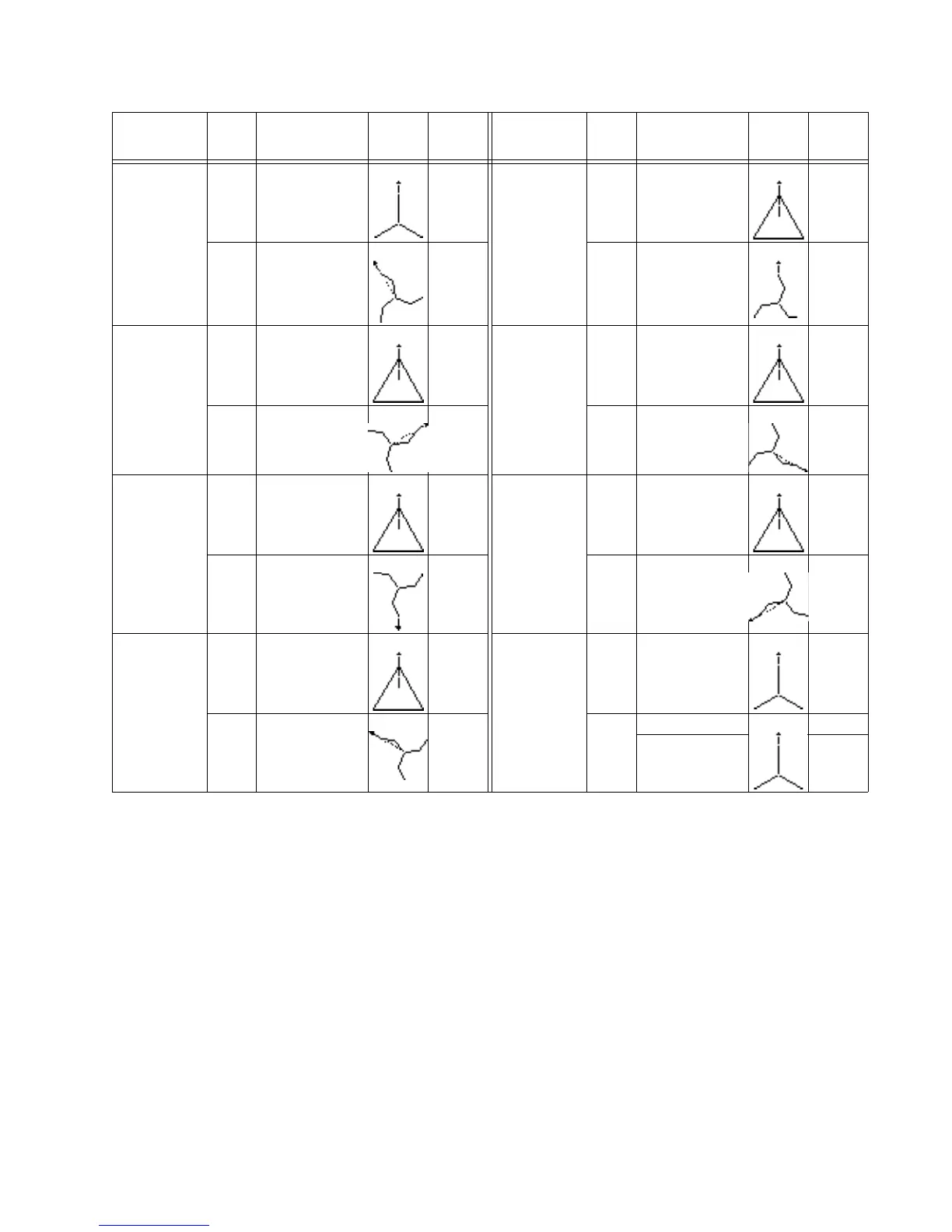
The following table shows the linear combination of phases of a transformer winding that
achieves the phase shift and zero sequence removal for typical values of Φ
comp
:
where:
I
A
[w] = uncompensated winding ‘w’ phase A current
I
A
p[w] = phase and zero sequence compensated winding ‘w’ phase A current.
Y/z330° 1 WYE (gnd 1/2) 330° lag D/z0° 1 DELTA (gnd 1/2) 0°
2 ZIG-ZAG (gnd 2/3)
330° lag
0° 2 ZIG-ZAG (gnd 2/3)
0° lag
0°
D/z60° 1 DELTA (gnd 1/2) 60° lag D/z120° 1 DELTA (gnd 1/2) 120° lag
2 ZIG-ZAG (gnd 2/3)
60° lag
0° 2 ZIG-ZAG (gnd 2/3)
120° lag
0°
D/z180° 1 DELTA (gnd 1/2) 180° lag D/z240° 1 DELTA (gnd 1/2) 240° lag
2 ZIG-ZAG (gnd 2/3)
180° lag
0° 2 ZIG-ZAG (gnd 2/3)
240° lag
0°
D/z300° 1 DELTA (gnd 1/2) 300° lag 3W External
Correction
1WYE 0°
2 ZIG-ZAG (gnd 2/3)
300° lag
0° 23 WYE 0° 0°
WYE 0° 0°
Transformer
Type
Wdg. Connection Voltage
Phasors
Phase
Shift
(Φ
comp
)
Transformer
Type
Wdg. Connection Voltage
Phasors
Phase
Shift
(Φ
comp
)