B-14 F35 Multiple Feeder Protection System GE Multilin
B.4 MEMORY MAPPING APPENDIX B
B
2342 Fault 1 Prefault Phase A Current Angle -359.9 to 0 degrees 0.1 F002 0
2343 Fault 1 Prefault Phase B Current Magnitude 0 to 999999.999 A 0.001 F060 0
2345 Fault 1 Prefault Phase B Current Angle -359.9 to 0 degrees 0.1 F002 0
2346 Fault 1 Prefault Phase C Current Magnitude 0 to 999999.999 A 0.001 F060 0
2348 Fault 1 Prefault Phase C Current Angle -359.9 to 0 degrees 0.1 F002 0
2349 Fault 1 Prefault Phase A Voltage Magnitude 0 to 999999.999 V 0.001 F060 0
234B Fault 1 Prefault Phase A Voltage Angle -359.9 to 0 degrees 0.1 F002 0
234C Fault 1 Prefault Phase B Voltage Magnitude 0 to 999999.999 V 0.001 F060 0
234E Fault 1 Prefault Phase B Voltage Angle -359.9 to 0 degrees 0.1 F002 0
234F Fault 1 Prefault Phase C Voltage Magnitude 0 to 999999.999 V 0.001 F060 0
2351 Fault 1 Prefault Phase C Voltage Angle -359.9 to 0 degrees 0.1 F002 0
2352 Fault 1 Phase A Current Magnitude 0 to 999999.999 A 0.001 F060 0
2354 Fault 1 Phase A Current Angle -359.9 to 0 degrees 0.1 F002 0
2355 Fault 1 Phase B Current Magnitude 0 to 999999.999 A 0.001 F060 0
2357 Fault 1 Phase B Current Angle -359.9 to 0 degrees 0.1 F002 0
2358 Fault 1 Phase C Current Magnitude 0 to 999999.999 A 0.001 F060 0
235A Fault 1 Phase C Current Angle -359.9 to 0 degrees 0.1 F002 0
235B Fault 1 Phase A Voltage Magnitude 0 to 999999.999 V 0.001 F060 0
235D Fault 1 Phase A Voltage Angle -359.9 to 0 degrees 0.1 F002 0
235E Fault 1 Phase B Voltage Magnitude 0 to 999999.999 V 0.001 F060 0
2360 Fault 1 Phase B Voltage Angle -359.9 to 0 degrees 0.1 F002 0
2361 Fault 1 Phase C Voltage Magnitude 0 to 999999.999 V 0.001 F060 0
2363 Fault 1 Phase C Voltage Angle -359.9 to 0 degrees 0.1 F002 0
2364 Fault 1 Type 0 to 11 --- 1 F148 0 (NA)
2365 Fault 1 Location based on Line length units (km or miles) -3276.7 to 3276.7 --- 0.1 F002 0
2366 ...Repeated for Fault 2
238C ...Repeated for Fault 3
23B2 ...Repeated for Fault 4
23D8 ...Repeated for Fault 5
Autoreclose Status (Read Only) (6 modules)
2410 Autoreclose 1 Count 0 to 65535 --- 1 F001 0
2411 Autoreclose 2 Count 0 to 65535 --- 1 F001 0
2412 Autoreclose 3 Count 0 to 65535 --- 1 F001 0
2413 Autoreclose 4 Count 0 to 65535 --- 1 F001 0
2414 Autoreclose 5 Count 0 to 65535 --- 1 F001 0
2415 Autoreclose 6 Count 0 to 65535 --- 1 F001 0
Expanded FlexStates (Read Only)
2B00 FlexStates, one per register (256 items) 0 to 1 --- 1 F108 0 (Off)
Expanded Digital Input/Output states (Read Only)
2D00 Contact Input States, one per register (96 items) 0 to 1 --- 1 F108 0 (Off)
2D80 Contact Output States, one per register (64 items) 0 to 1 --- 1 F108 0 (Off)
2E00 Virtual Output States, one per register (96 items) 0 to 1 --- 1 F108 0 (Off)
Expanded Remote Input/Output Status (Read Only)
2F00 Remote Device States, one per register (16 items) 0 to 1 --- 1 F155 0 (Offline)
2F80 Remote Input States, one per register (64 items) 0 to 1 --- 1 F108 0 (Off)
Oscillography Values (Read Only)
3000 Oscillography Number of Triggers 0 to 65535 --- 1 F001 0
3001 Oscillography Available Records 0 to 65535 --- 1 F001 0
3002 Oscillography Last Cleared Date 0 to 400000000 --- 1 F050 0
3004 Oscillography Number Of Cycles Per Record 0 to 65535 --- 1 F001 0
Oscillography Commands (Read/Write Command)
3005 Oscillography Force Trigger 0 to 1 --- 1 F126 0 (No)
3011 Oscillography Clear Data 0 to 1 --- 1 F126 0 (No)
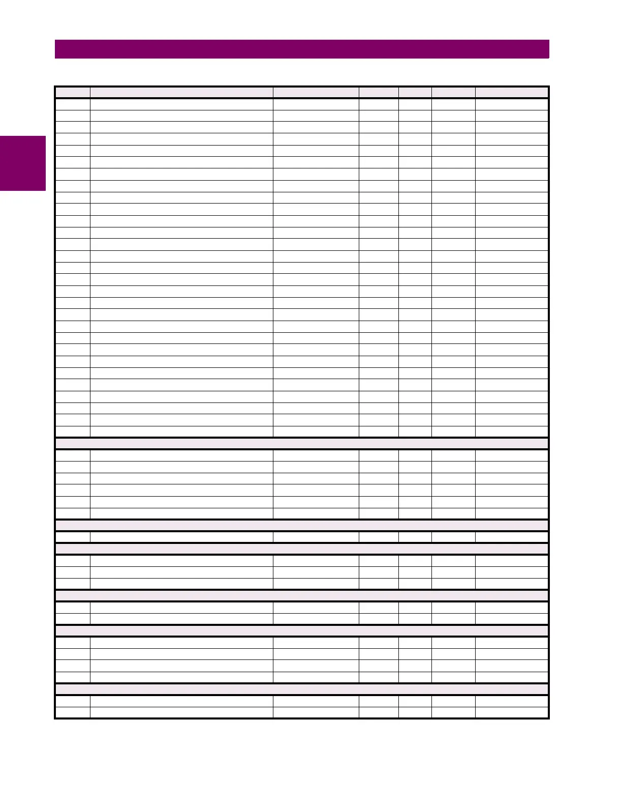
Table B–9: MODBUS MEMORY MAP (Sheet 7 of 48)
ADDR REGISTER NAME RANGE UNITS STEP FORMAT DEFAULT