CHAPTER 5: SETPOINTS S2 SYSTEM SETUP
745 TRANSFORMER PROTECTION SYSTEM – INSTRUCTION MANUAL 5–43
5.4.11 Analog Outputs 1 to 7
PATH: SETPOINTS S2 SYSTEM SETUP ANALOG OUTPUTS ANALOG OUTPUT 1(7)
There are seven analog outputs on the 745 relay which are selected to provide a full-scale
output range of one of 0 to 1 mA, 0 to 5 mA, 4 to 20 mA, 0 to 20 mA or 0 to 10 mA. Each
channel can be programmed to monitor any measured parameter. This sub-section is only
displayed with the option installed.
• ANALOG OUTPUT 1(7) FUNCTION: This message enables or disables the analog
output 1(7) feature. When disabled, 0 mA will appear at the corresponding terminal.
• ANALOG OUTPUT 1(7) VALUE: Select the measured parameter below to be
represented by the mA DC current level of analog output 1(7).
• ANALOG OUPUT 1(7) RANGE: Select the full-scale range of output current for analog
output 1(7).
• ANALOG OUTPUT 1(7) MIN/MAX: Enter the value of the selected parameter which
corresponds to the minimum/maximum output current of analog output 1(7).
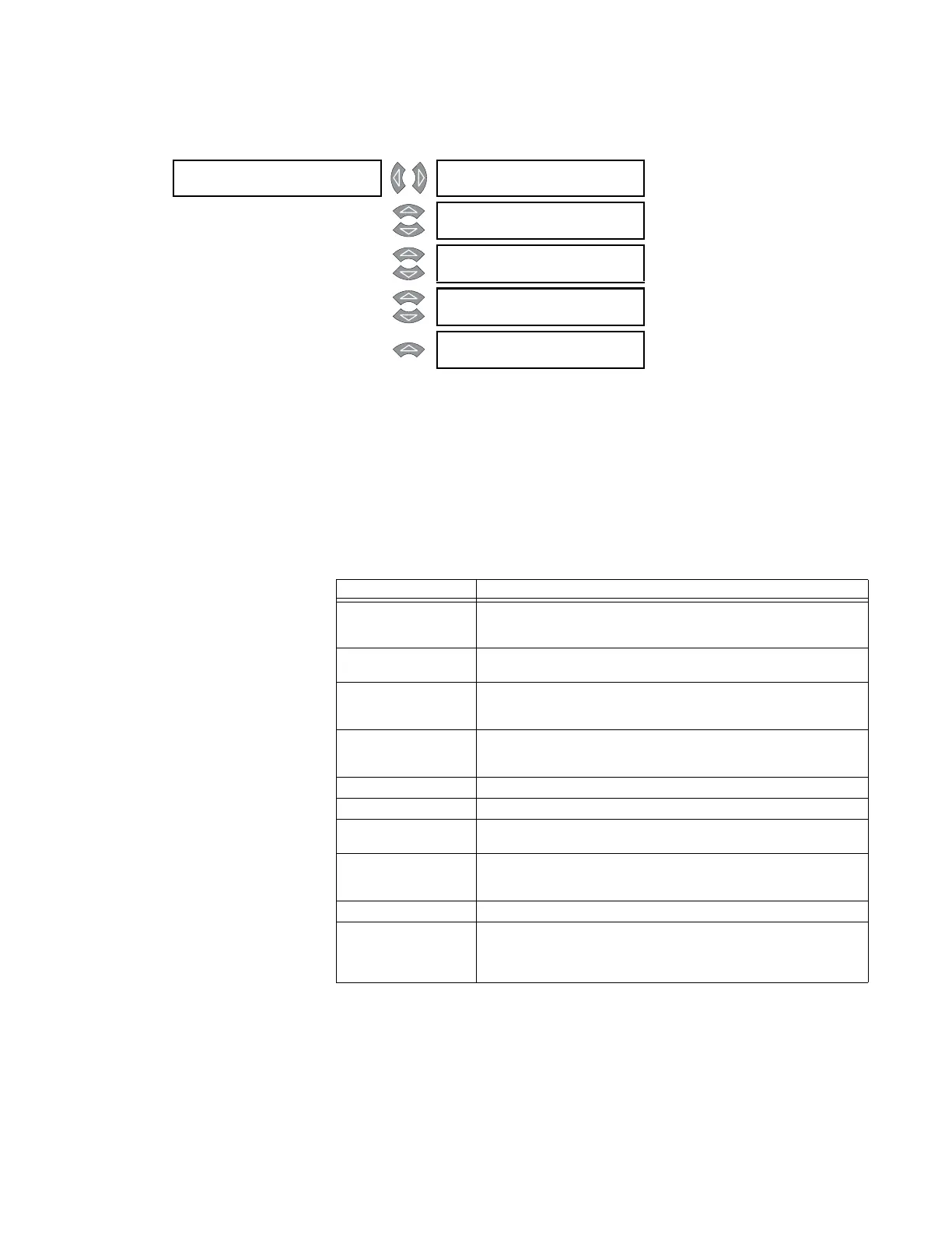
ANALOG OUTPUT 1 [] ANALOG OUTPUT 1
FUNCTION: Disabled
Range: Enabled, Disabled
MESSAGE
ANALOG OUTPUT 1
VALUE: W1 ΦA Current
Range: see table below
MESSAGE
ANALOG OUTPUT 1
RANGE: 4-20 mA
Range: 0-1 mA, 0-5 mA, 4-20 mA, 0-20
mA, 0-10 mA
MESSAGE
ANALOG OUTPUT 1
MIN: 0 A
Range: matches the range of the
selected measured parameter
MESSAGE
ANALOG OUTPUT 1
MAX: 1000 A
Range: matches the range of the
associated actual value
Parameter Description
W1(3) ΦA Current
W1(3) ΦB Current
W1(3) ΦC Current
Select to monitor the RMS value (at fundamental frequency) of the
winding 1(3) Phase A, B, and C current inputs.
W1(3) Loading Select to monitor the winding 1(3) load as a percentage of the rated
load for that winding.
W1(3) ΦA THD
W1(3) ΦB THD
W1(3) ΦC THD
Select to monitor the total harmonic distortion in the winding 1(3)
phase A, B, and C current inputs.
W1(3) Derating Select to monitor the harmonic derating factor (that is, the derated
transformer capability while supplying non-sinusoidal load currents)
in winding 1(3).
Frequency Select to monitor the system frequency.
Tap Position Select to monitor the onload tap changer position.
Voltage Select to monitor the system voltage as measured from the voltage
input.
W1(3) ΦA Demand
W1(3) ΦB Demand
W1(3) ΦC Demand
Select to monitor the current demand value of the winding 1(3)
phase A, B, and C current inputs.
Analog Input Select to monitor the general purpose analog input current.
MaxEvnt W1(3) Ia
MaxEvnt W1(3) Ib
MaxEvnt W1(3) Ic
MaxEvnt W1(3) Ia
Select to monitor the maximum captured RMS value (at fundamental
frequency) of the winding 1(3) phase A, B, C, and ground current
input for all events since the last time the event recorder was
cleared.
 Loading...


