5–44 745 TRANSFORMER PROTECTION SYSTEM – INSTRUCTION MANUAL
S3 LOGIC INPUTS CHAPTER 5: SETPOINTS
5.5 S3 Logic Inputs
5.5.1 Description
The are two types of digital inputs: Logic inputs have physical terminals for connecting to
external contacts; Virtual inputs provide the same function as logic inputs, but have no
physical external connections. A setpoint defines the state of each in virtual input in terms
of “On” or “Off”.
There are sixteen each of logic and virtual inputs. The state (‘asserted’ or ‘not asserted’) of
each logic or virtual input can be used to activate a variety of predefined logic functions,
such as protection element blocking, energization detection, etc. In addition, any logic or
virtual input can be used as an input in FlexLogic™ equations to implement custom
schemes.
5.5.2 Logic Inputs 1 to 16
PATH: SETPOINTS S3 LOGIC INPUTS LOGIC INPUTS LOGIC INPUT 1(16)
• INPUT 1(16) FUNCTION: Select “Enabled” if this logic input is to be used. Selecting
“Disabled” prevents this logic input from achieving the asserted (or signaling) state.
• INPUT 1(16) TARGET: Selecting “None” inhibits target message display when the input
is asserted. Thus, an input with target type “None” never disables the LED self-test
feature since it cannot generate a displayable target message.
• INPUT 1(16) NAME: Press ENTER to edit the login input name. The text may be
changed from “Logic Input 1” one character at a time with the VALUE keys. Press
ENTER to store and advance to the next character position.
• INPUT 1(16) ASSERTED STATE: Select “Closed” as when connected to a normally open
contact (where the signaling state is closed). Select “Open” when connected to a
normally closed contact (where the signaling state is open).
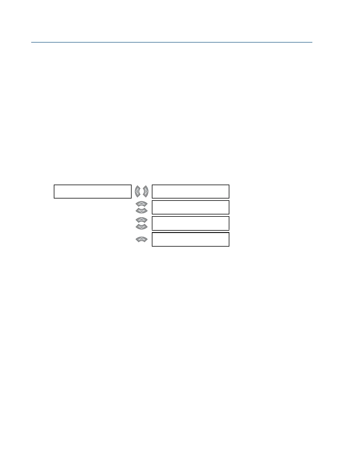
LOGIC INPUT 1 [] INPUT 1 FUNCTION:
Disabled
Range: Enabled, Disabled
MESSAGE
INPUT 1 TARGET:
Self-Reset
Range: None, Latched, Self-Reset
MESSAGE
INPUT 1 NAME:
Logic Input 1
Range: 18 alphanumeric characters
MESSAGE
INPUT 1 ASSERTED
STATE: Closed
Range: Open, Closed